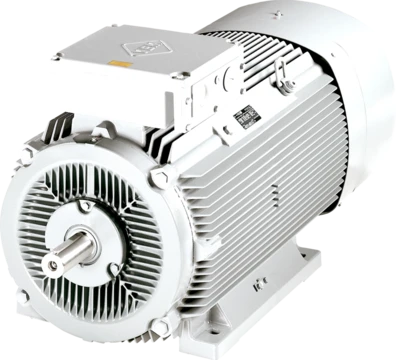
Drum motor
A sealed, single-component drive pulley for conveyor belts.

A drum motor (also called a motorised pulley) is a single-component drive unit for conveyor belts. It consists of a geared motor completely sealed inside a steel shell, which acts as the driving pulley. The concept was first recorded in 1928, but the first industrial versions were not produced until the early 1950s, specifically for conveyor belt use. The design aimed to create a compact, fully enclosed drive with high efficiency and less friction than a standard geared motor. Today, drum motors are used in airport check-in conveyors, security scanners, supermarket checkouts, food processing lines, weighing equipment, and reversible versions power roller shutter doors.
In the basic design, an electric motor (asynchronous, synchronous, or hydraulic) is fixed to a stationary shaft. One end of the drum connects through the motor’s rotor pinion to an in-line helical or planetary gearbox, which is fixed to the other stationary shaft. Torque passes from the motor through the gearbox to the drum shell via a coupling or geared rim attached to the shell or end housing. Because of this in-line transmission (using two or three stages of helical or planetary gears), up to 95% of the motor’s output power typically reaches the drum shell. Gears can be made from high-grade steel, sintered metal, or polymers.
Electrical cables or hydraulic hoses connect through one of the stationary shafts and are sealed with compression seals. Shaft and connection seals use materials like NBR, FPM, or carbon. Lubrication is done with oil or grease; oil also helps cool the motor, though some motors are air-cooled. The drum shell (or pulley face) can be made of aluminum, steel, or stainless steel and is usually crowned to help center the belt. Cylindrical shells are also available, fitted with external sprockets or rotary brushes for special uses. Rubber, NBR, PU, or other coatings can be applied to increase friction with the belt, and hot-vulcanized or molded profiled lagging can drive plastic or steel modular belts.
The exposed drum shafts do not rotate; they are used to mount the drum motor in the conveyor frame. A single “through” shaft design, where the motor and gearbox are fixed with keys or pins, has limited radial load capacity due to bending stress from belt tension, so it is mainly for light-duty conveyors.
- First recorded concept
- 1928
- First industrial production
- early 1950s
- First industrial designer
- John Kirkegaard
- Efficiency transmission
- up to 95%
- Temperature range
- -40 to 50 °C (-40 to 122 °F)
- Early patent application year
- 1932
- Patent application origin
- Pittsburgh subsidiary of Schloemann
Lore & Background
The drum motor concept was first recorded in 1928, but it was not used until the early 1950s, when it was first produced specifically for conveyor belt applications. The goal was to produce a compact, totally enclosed single component drive unit with high efficiency and lower frictional losses compared to a conventional geared motor. An early description of a drum motor appears in a 1932 United States patent, with the application filed in November 1928 by the Pittsburgh subsidiary of the German engineering company Schloemann. Twenty years later, in the early 1950s, Danish inventor and entrepreneur John Kirkegaard designed the first industrial-type drum motor.
The drum motor uses an asynchronous or synchronous electric motor, or hydraulic motor, fixed to a stationary shaft. One end of the drum is directly coupled through the motor's rotor pinion to an in-line helical or planetary gearbox fixed to the other stationary shaft. Torque is transferred from the motor via the gearbox to the drum shell through a coupling or geared rim. The drum shell can be made of aluminum, steel, or stainless steel, and is normally crowned to facilitate central belt tracking. Rubber, NBR, PU, and other coatings can be applied to increase friction, and hot vulcanized or molded profiled lagging can drive plastic or steel modular belts.
Drum motors can be designed to work in temperatures from -40 to 50 °C and can withstand high-pressure water jets, chemical cleaning, and extremely dusty conditions. They can be installed horizontally or vertically and used in non-conveyor belt applications. Most drum motors require zero or minimal maintenance, which means higher productivity and less downtime. Because the drum motor is totally enclosed, it cannot contaminate food, electrical equipment, or pharmaceutical substances, and when manufactured in stainless steel, it can be hygienically cleaned and sanitized regularly.
Reader's Guide
The drum motor's significance lies in its consolidation of motor, gearbox, and bearings into a single sealed shell, eliminating the need for up to eight separate components typical of conventional drives. This reduces inventory costs and simplifies installation, as only the drum motor and two fixing brackets are required. The design is notably lighter than conventional drives, with weight evenly distributed within the conveyor frame. Its enclosed construction makes it unlikely to fail due to harmful environmental conditions such as water, dust, dirt, grit, chemicals, grease, and oil. The drum motor is considered the most hygienic conveyor drive design to date, as its smooth, clean profile allows for quick and easy cleaning with high-pressure water, steam, or chemicals, often reducing operating costs, especially in food processing applications. Today, drum motors are found in airport check-in conveyors and security machines, supermarket check stands, food processing conveyors, weighing equipment, and reversible drum motors are used for roller shutter doors. Alternative designs include backstop non-reversing bearings for inclined conveyors, electro-magnetic brakes for reversible inclined conveyors, and integrated incremental encoders for closed-loop control systems.
More in Electric Motors 1-24
Spotted an error? Know more?
Reader corrections go straight into our review queue. Suggest an edit · How this site is sourced