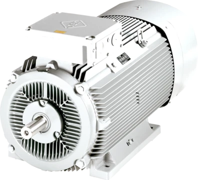
Armature (electrical)
Armature carries current and generates electromotive force in motors and generators.

An armature is the winding or set of windings of an electric machine that carries alternating current. In DC machines, the armature windings conduct AC due to commutator action or electronic commutation, as in brushless DC motors. The armature can be located on either the rotor or the stator, depending on the machine type.
- First electrical use
- mid 19th century
- Armature shapes
- double-T and triple-T
- Armature winding materials
- copper or aluminum
- Armature reaction correction methods
- brush shifting and interpoles
- Small generator threshold
- approximately 1,000 W or less
Lore & Background
The word armature was first used in its electrical sense, meaning keeper of a magnet, in the mid 19th century. In most generators, the field magnet rotates as part of the rotor, while the armature is stationary and part of the stator. However, both motors and generators can be built with either a stationary armature and rotating field or a rotating armature and stationary field. The pole piece of a permanent magnet or electromagnet and the moving iron part of a solenoid may also be referred to as armatures.
In a DC machine, two sources of magnetic flux exist: armature flux and main field flux. The effect of armature flux on the main field flux is called armature reaction, which changes the distribution of the magnetic field and shifts the neutral plane. The neutral plane is the position where armature windings move parallel to magnetic flux lines. Without armature reaction, the magnetic neutral axis (MNA) coincides with the geometrical neutral axis (GNA). Armature reaction causes the neutral plane to shift in the direction of rotation.
Two principal methods overcome armature reaction: shifting the brush position so they are in the neutral plane at normal load, or installing interpoles. The brush-setting method is satisfactory for constant loads and is common in small generators (approximately 1,000 W or less). Larger generators require interpoles. Armature reaction is essential in amplidyne rotating amplifiers.
Reader's Guide
The armature is a fundamental component in electric machines, serving the dual role of carrying current across the magnetic field to create torque or force, and generating an electromotive force (EMF). In motors, this EMF opposes the armature current, converting electrical power to mechanical power via the shaft. In generators, the armature EMF drives the current, converting shaft movement to electrical power. The armature's design—whether lap or wave winding—affects current paths and suitability for different voltage and current ratings. Lap windings have as many current paths as poles, while wave windings have only two paths. The choice of winding materials (copper for higher conductivity, aluminum for lighter weight and lower cost) influences efficiency and cost. Armature reaction, the distortion of the main field by armature flux, is a critical consideration in DC machines, requiring corrective measures such as brush shifting or interpoles to maintain proper commutation and avoid arcing. The growler is a tool used to check armatures for short circuits, open circuits, and leakages to ground. The terminology can cause confusion because mechanical and electrical terms are often used interchangeably, especially in compound machines like brushless alternators.
Did You Know?
- The armature windings conduct AC even on DC machines, due to commutator action or electronic commutation.
- A growler is used to check the armature for short and open circuits and leakages to ground.
The Dual Role of the Armature
The armature sits at the heart of every electric machine, serving two simultaneous functions that define whether the device operates as a motor or a generator. At its core, the armature is a conductive winding—always a coil or set of coils—positioned so that it cuts across the magnetic flux in the air-gap. That flux may come from permanent magnets or from electromagnets wound with conducting wire. Because the armature must carry alternating current, even in machines nominally rated for DC, the commutator periodically reverses current direction, or electronic commutation handles the task in brushless DC designs.
The first role of the armature is to carry current across the field, producing shaft torque in a rotating machine or linear force in a straight-line machine. The second role is to generate an electromotive force through the relative motion between the winding and the field. In motor mode, this induced EMF opposes the applied current, and electrical power is converted into mechanical rotation delivered through the shaft. In generator mode, the relationship inverts: the EMF drives the current, and mechanical input becomes electrical output. In an induction generator specifically, the generated power is drawn from the stator side.
Armature Reaction and the Shifting Neutral Plane
In any DC machine, two distinct magnetic fluxes coexist: the main field flux and the flux generated by the armature coils themselves. Whenever current flows through those windings, a magnetic field appears at right angles to the main field—a phenomenon called cross magnetization. This armature flux distorts the main field and shifts the magnetic neutral axis away from its no-load position. The neutral plane is the orientation where armature conductors travel parallel to the flux lines and thus produce no EMF.
At no load, the magnetic neutral axis aligns with the geometrical neutral axis, which bisects the angle between adjacent pole centers. As armature current builds, however, the neutral plane drifts in the direction of rotation, proportional to the current. This creates a practical problem: brushes must contact commutator segments tied to coils carrying zero induced EMF. Contacting live coils instead causes arcing and power loss.
Engineers correct the shift in two principal ways. For small generators producing roughly a kilowatt or less, repositioning the brushes to the loaded neutral plane works well, provided the load remains fairly constant. Larger machines depend on interpoles—special field poles wired into the armature circuit—or on compensating windings added to the main poles. Armature reaction is not merely a nuisance; it is deliberately harnessed in amplidyne rotating amplifiers.
Naming, Configuration, and the Rotor-Stator Question
The word "armature" entered electrical vocabulary in the mid-nineteenth century, originally meaning the keeper of a magnet. Over time its meaning broadened to cover the current-carrying winding of any electric machine, yet the term still carries echoes of its mechanical origins. In fact, the pole piece of a permanent magnet or electromagnet, and the moving iron core of a solenoid acting as a switch or relay, may all be called armatures.
A persistent source of confusion in the field is the dual vocabulary used to describe alternators and related equipment. Parts can be named in mechanical terms (rotor, stator) or in electrical terms (armature, field), and practitioners frequently mix the two. This ambiguity becomes especially thorny with compound machines such as brushless alternators, or when engineers accustomed to different configurations discuss the same component.
In most generators, the field magnet rotates as part of the rotor while the armature remains stationary on the stator. Yet both motors and generators can be built with either a rotating armature and stationary field, or the reverse. The armature may therefore sit on the spinning element or the fixed frame, depending entirely on the machine's design philosophy. This flexibility means that no single rule dictates which part is the armature; the electrical function, not the mechanical position, defines it.
Winding Geometries and Practical Diagnostics
The physical shape of an armature is far from arbitrary. Motor designers have settled on distinctive cross-sectional profiles, most notably the double-T and triple-T armatures, whose geometry channels magnetic flux through the iron core. The individual coils are distributed across the entire surface of the air gap, whether that gap belongs to the rotor or the stator. In a lap winding, the arrangement determines the number of parallel current paths between the brush or line connections, creating an electrical topology that governs how current divides through the machine.
Because the armature is fundamentally a bundle of wire coils, it is vulnerable to short circuits between turns, open circuits where a wire has broken, and leakages to ground where insulation has degraded. A growler—a specialized diagnostic instrument—allows a technician to detect all three failure modes without disassembling the machine. By inducing a low-frequency signal through the winding and listening for characteristic hum patterns, the growler reveals whether a coil is intact, shorted, or grounded.
The commutator, when present, periodically reverses current direction in each coil as the armature rotates, ensuring torque always acts in the same direction. In brushless DC motors, electronic commutation replaces the mechanical commutator entirely, but the principle of the armature carrying alternating current through the field remains unchanged.
Frequently Asked Questions
What is an armature in an electric motor?
An armature is the set of windings inside an electric machine that carries alternating current and produces electromotive force. It has served as a core component of electrical machines since the mid-19th century.
Is the armature always mounted on the rotor?
No — depending on the machine design, the armature windings can sit on either the rotating part (rotor) or the stationary part (stator). Which side carries the armature depends on the specific type of motor or generator.
What materials and shapes are used for armature windings?
Armature windings are typically wound from copper or aluminum conductors. They are commonly formed into double-T or triple-T cross-sectional profiles to pack as much conductor into the slot space as possible.
How does the armature carry AC inside a DC motor?
Even in a DC machine, the individual armature windings actually conduct alternating current because the commutator (or electronic commutation in brushless designs) flips the current direction each time a winding passes a pole. This is what keeps the torque direction consistent as the rotor spins.
What is armature reaction and how do engineers fix it?
Armature reaction is the distortion of the main magnetic field caused by current flowing through the armature windings. The two classic correction methods are shifting the brush position and inserting interpoles to counteract the unwanted flux shift.
More in Electric Motors 1-24
Spotted an error? Know more?
Reader corrections go straight into our review queue. Suggest an edit · How this site is sourced