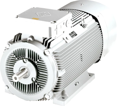
Braking chopper
Braking choppers limit DC bus voltage by switching energy to a resistor.

A braking chopper, also referred to as a braking unit, is a device used in the DC voltage intermediate circuits of frequency converters to control voltage when a load feeds energy back to the intermediate circuit. This occurs, for example, when a magnetized motor is rotated by an overhauling load and functions as a generator. The braking chopper applies the chopper principle, using on-off control of a switching device to limit DC bus voltage by switching braking energy to a resistor, where it is converted to heat.
- Activation condition
- Automatically activated when actual DC bus voltage exceeds a specified level depending on nominal voltage of the variable-frequency drive
- Typical dimensioning cycle
- 100% power 1/10 minutes
- Instantaneous braking power example
- Several hundred kW for several minutes
- Low power motor threshold for flux braki
- Below 5 kW
Lore & Background
Braking choppers are an application of the chopper principle, using on-off control of a switching device. They are automatically activated when the actual DC bus voltage exceeds a specified level depending on the nominal voltage of the variable-frequency drive. The braking energy is converted to heat in a resistor. The technology is described as having simple electrical construction and being well-known. Braking choppers work even if AC supply is lost, which may be required for safety-related applications such as elevators. Drawbacks include wasted braking energy if the heated air cannot be used, additional space requirements for the chopper and resistors, possible extra investments in cooling and heat recovery, and increased risk of fire due to hot resistor and ambient dust or chemicals. The increased DC bus voltage during braking also causes additional voltage stress on motor insulation. Braking choppers are typically dimensioned for a certain cycle, such as 100% power for 1/10 minutes, and long braking times require more accurate dimensioning.
Reader's Guide
The significance of the braking chopper lies in its role in managing regenerative energy in frequency converter systems, particularly when loads feed power back into the DC intermediate circuit. It is notable for its simple construction and ability to function during main power loss, which is critical in safety applications like elevators. However, its drawbacks include energy waste as heat, additional space and cooling requirements, and fire risk in dusty or chemical environments. The article also describes flux braking as an alternative method based on motor losses, where motor flux and magnetizing current are increased to handle overrunning loads. Flux braking is most effective in low power motors (below 5 kW) due to their relatively high resistance values. The braking chopper remains appropriate for continuous or regularly repeated braking, high total braking energy relative to motoring energy, high instantaneous braking power (e.g., several hundred kW for minutes), and braking needed during power loss. It is inappropriate for occasional braking cycles, very small braking energy amounts, or ambient air with combustible or metallic components.
Core Operating Principle
A braking chopper functions as a magnetic switching device that safeguards the DC voltage intermediate circuit inside a frequency converter. Its critical role surfaces when a magnetized motor, spun by an overhauling load, effectively acts as a generator and pours energy back into the DC bus. The chopper continuously monitors bus voltage and, the instant it crosses a threshold set by the drive's nominal voltage, it engages automatically. Once triggered, the switching device rapidly toggles between on and off states, routing the surplus braking energy into a dedicated resistor where it is converted into heat. This on-off modulation of a switching element is the fundamental chopper principle repurposed for a braking context. The whole arrangement exists to absorb the load's kinetic energy before overvoltage can damage the converter's internal components.
Where They Excel and Where They Fall Short
Braking choppers are well matched to situations where braking is continuous or regularly repeated, where total braking energy dwarfs the motoring energy required, and where instantaneous braking power reaches several hundred kilowatts sustained over minutes. A standout advantage is that the chopper keeps working even when the AC supply drops, a feature that proves indispensable in safety-critical settings such as elevators where controlled deceleration during a power outage is mandatory. On the other hand, the technology is poorly suited when braking is only occasional, when braking energy is negligible relative to motoring energy, or when the surrounding air carries substantial dust, combustible, explosive, or metallic particles. The chopper must also be carefully dimensioned for its duty cycle, for example 100 percent power for one-tenth of a minute, so extended braking durations demand more precise engineering of the unit.
Trade-offs in Cost, Space, and Safety
The braking chopper offers a straightforward electrical architecture built on well-established technology, keeping the fundamental investment in both the chopper and its companion resistor relatively modest. Its independence from the AC supply adds a safety layer that alternative methods may lack. The trade-offs, however, are considerable. Braking energy is entirely wasted as heat unless the warmed air can be captured and reused, potentially forcing additional cooling or heat-recovery infrastructure. The chopper and resistor assembly also claim extra physical space within the installation. Prolonged operation heats the resistor, elevating fire risk especially in environments containing dust or chemical contaminants. Moreover, the elevated DC bus voltage during braking places additional electrical stress on the motor's insulation, a factor that must be weighed in long-term reliability planning.
Flux Braking: A Motor-Centric Alternative
An alternative to the external-resistor approach is flux braking, which harnesses the motor's own internal losses to handle an overrunning load. Under this method, the motor's flux and magnetizing current are deliberately raised during braking, a control task readily accomplished through the direct torque control principle. With DTC, the inverter is steered directly to hit the target torque and flux, ensuring braking follows a specified speed ramp. This contrasts sharply with DC injection braking, where DC current is forced into the motor and flux control is lost. A key advantage of the DTC-based approach is the motor's ability to snap back from braking to motoring power on demand. The increased current elevates winding losses, so braking power rises even though the power delivered to the converter does not. Because higher resistance relative to nominal current yields greater dissipation, the technique is most effective in low-power motors below five kilowatts, where winding resistance is proportionally larger.
Frequently Asked Questions
Who is Braking chopper?
A braking chopper, also known as a braking unit, is a voltage-control device that sits in the DC intermediate circuit of a frequency converter. Its job is to step in whenever a load pushes energy back toward the bus, such as when an overhauling load spins a magnetized motor into generator mode.
What are Braking chopper's powers/role?
It applies the chopper principle by rapidly switching a device on and off, diverting surplus braking energy into a resistor so the DC bus voltage stays within safe limits. In practice this can absorb several hundred kilowatts of instantaneous power for a few minutes at a time.
Why is Braking chopper important?
Without it, a motor driven into generation by an overhauling load would dump uncontrolled energy into the DC bus, potentially destroying the variable-frequency drive. It is especially critical for motors above roughly 5 kW, where simple flux braking is no longer sufficient.
When does Braking chopper activate?
It engages automatically the instant the actual DC bus voltage exceeds a threshold tied to the drive's nominal voltage rating. Its typical dimensioning cycle calls for 100 % rated power for one minute out of every ten minutes of operation.
More in Electric Motors 1-24
Spotted an error? Know more?
Reader corrections go straight into our review queue. Suggest an edit · How this site is sourced