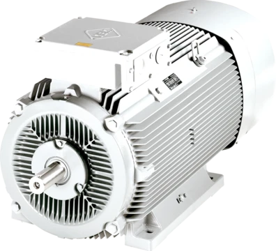
Bipolar electric motor
A two-pole stationary field motor used from early DC motors to modern appliances.

A bipolar electric motor has only two poles in its stationary field, making it a basic brushed DC motor with a commutator. That stationary field can come from either a permanent magnet or a field coil. The name "bipolar" applies to the stationary field, not the rotor—rotors frequently have more than two poles. If the rotor itself has only two poles, the motor won't start from every position and needs a manual flick to get going.
Early DC motors, starting with the Gramme motor in the 1870s, all used bipolar fields. Their field pole pieces were crudely built, with long magnetic circuits, wide pole gaps, and narrow poles that delivered only limited flux to the armature. These fields were usually horseshoe-shaped, using either permanent horseshoe magnets or one or two field coils set some distance from the poles. Early insulated wire was wrapped in cotton thread, if insulated at all, so the coils could only handle a low temperature rise before overheating and shorting out. To avoid that, coils were long and shallow—sometimes just a single layer of wire—requiring a long core just to hold them. A single small coil could be mounted horizontally, but the most common setup used two tall coils side by side.
To make the magnetic circuit more efficient, engineers realized they could send multiple magnetic paths through the same armature. The two coils were separated and placed at the motor's sides, with their iron cores forming a sideways figure-8 circuit and the armature sitting in a central pole gap. Flux from both coils passed through that gap, shortening the overall magnetic circuit and cutting magnetic losses. More compact coil windings became possible thanks to shellac, which impregnated the windings and made their insulation more reliable.
Around 1900, designs grew more compact with shorter, more efficient magnetic circuits. Field coils moved into short, squat internal coils right around the pole pieces themselves. The rest of the magnetic circuit became a double-sided circular path around the motor casing. While the main goal was efficiency, this also saved a lot of space. That circular layout marked the end of the bipolar motor as an industrial power source, because a second set of field coils and pole pieces could fit inside the same casing, creating a four-pole arrangement.
- Earliest example
- Gramme motor of the 1870s
- Later design compact around
- 1900
- Last industrial use
- Milwaukee Road class EP-2 electric locomotives of 1917
- Voltage of ep-2
- 3,000 V DC
- Operational lifespan of ep-2
- 35 years
- Withdrawal reasons
- decline in US railroads in the late 1950s, advent of cheap diesel power, poorly carried out rebuilding
Lore & Background
The first DC electrical motors, from the Gramme motor of the 1870s onwards, used bipolar fields. These early machines had crudely designed field pole pieces with long magnetic circuits, wide pole gaps, and narrow pole pieces that gave limited flux through the armature. Fields were usually horseshoe-shaped, with either permanent horseshoe magnets or one or two field coils at some distance from the poles. Early insulated wire used wrappings of cotton thread, limiting temperature rise. Coils were long and shallow, sometimes single-layer, requiring a long core. The most common arrangement used two tall coils side by side. To improve efficiency, multiple magnetic paths were provided through the same armature, with two coils separated and placed at the sides, their iron core forming a sideways figure-8 circuit and the armature in a central pole gap. This gave a shorter magnetic circuit with fewer losses. More compact windings were made possible by shellac impregnation. Later designs around 1900 became more compact with shorter magnetic circuits, field coils moving into short, squat internal coils around the pole pieces, and the remainder of the magnetic circuit forming a double-sided circular path around the casing. This circular layout allowed placing a second set of field coils and pole pieces within the same casing, giving a four-pole arrangement of almost twice the power for the same armature current, marking the end of the bipolar motor as an industrial power source.
Reader's Guide
One of the last industrial uses for large bipolar motors was for the Milwaukee Road's class EP-2 electric locomotives of 1917, which used 3,000 V DC. These locomotives used axle-mounted motors driving each wheel directly, with the axle forming the spindle of the motor armature. To permit use for powerful locomotives, the motor was split in two: the armature was part of the axle, while the heavier field poles and coils were carried on the suspended frame. This required the armature to move up and down relative to the field as the suspension moved. With a four-pole motor, this would vary the pole gap and cause the armature to hit the pole pieces. The solution was to return to the bipolar motor, placing poles at the side of the armature with flat vertical faces, allowing free vertical movement. The design was relatively inefficient, but the locomotives were designed for power and haulage capacity with cheap hydro-electricity. The EP-2 locomotives operated reliably for 35 years, withdrawn due to decline in US railroads, cheap diesel power, and a poorly carried out rebuilding. The bipolar motor remains in widespread use today in medium-power, low-cost applications such as universal motors in home appliances (food mixers, vacuum cleaners, electric drills). These motors are brushed DC motors with series-connected field windings, also working well on AC supplies. They offer greater torque and speed than induction motors, making them valuable where capital cost and light weight are more important than electrical efficiency.
Did You Know?
- A two-pole rotor is not self-starting in all positions and requires a flick to start.
- The Milwaukee Road's class EP-2 locomotives were so associated with the bipolar motor that they were nicknamed 'Bi-Polar'.
- Early bipolar motors used horseshoe-shaped fields with either permanent magnets or field coils.
- The Taycol range of model motors used wound fields, with a single transverse coil or dual vertical coils.
The Pulse-to-Step Conversion Principle
A stepper motor is a brushless DC device whose defining characteristic is the ability to translate a sequence of electrical pulses—typically square waves—into exact, incremental changes in shaft angle. Unlike a conventional brushed DC motor that spins freely once voltage is applied, a stepper motor advances by a fixed angular increment for every pulse it receives, and it can be commanded to hold a specific position without any external position sensor providing feedback. The internal construction consists of several toothed electromagnets arranged in a circular stator surrounding a central gear-shaped iron rotor. When one electromagnet is energized, it magnetically pulls the nearest teeth of the rotor into alignment. Because those teeth are slightly offset from the adjacent electromagnet, switching power to the next magnet and off from the first causes the rotor to rotate a small additional amount. Repeating this sequential energization produces continuous rotation, while stopping at any point locks the shaft at a precise angle. The number of such partial rotations required for one full turn is an integer, giving the designer exact angular control.
Three Architectural Families
Stepper motors fall into three principal categories, each exploiting a different magnetic interaction. Permanent magnet designs place a fixed magnet in the rotor, so movement results from attraction or repulsion between that rotor magnet and the stator coils. A notable feature is the detent: when the motor is powered and parked at a step, a strong holding torque with a predictable spring rate resists displacement, and slippage only occurs if that torque limit is exceeded. Even after power is removed, a weaker detent persists, keeping the shaft in place against light loads. Variable reluctance motors use a soft iron rotor instead, relying on the principle that the rotor seeks the position of minimum magnetic gap. These motors exhibit detents only while energized. Hybrid synchronous motors merge both approaches—combining a permanent magnet rotor with variable-reluctance geometry—to extract maximum torque from a compact package. Because none of these types requires a position readout, applications such as paper printers, 3D printers, and robotics simply count the number of steps commanded to track shaft location.
Bipolar Winding Topology and Drive Electronics
In a bipolar stepper motor, each phase consists of a pair of single-winding connections rather than a center-tapped coil. This means there is no common wire; instead, two leads per phase carry current in opposite directions to flip the magnetic polarity. Reversing the magnetic pole therefore demands that the current direction through the winding be reversed, which in turn requires a more sophisticated driving circuit—most commonly an H-bridge arrangement. Fortunately, several off-the-shelf driver chips simplify what would otherwise be a complex switching task. A typical energization sequence for a two-coil bipolar motor follows this pattern: drive coil A with positive current, remove current from A, drive coil B with positive current, remove current from B, then drive coil A with negative current (achieved by flipping polarity through the H-bridge), and finally remove current from A. This four-step cycle, repeated, produces continuous rotation. The absence of a center tap and the need for bidirectional current make bipolar motors slightly more demanding to wire and drive than their unipolar counterparts, but they offer the advantage of using the full winding in every step.
Practical Identification, Testing, and Application Context
Distinguishing and testing stepper motor windings is a common task for hobbyists and engineers alike. In a unipolar motor, each phase has a center tap, yielding three leads per phase (or five total when the two phase commons are internally joined). The center tap can be identified by measuring resistance: the resistance from the common lead to either coil-end is exactly half of what you measure across the two coil-ends, because the coil length from center to end is half the full winding. A quick functional test involves shorting pairs of terminals and attempting to turn the shaft; a noticeable increase in turning resistance indicates that a particular winding circuit is closed and the phase is operational. Bipolar motors, by contrast, present only two leads per phase with no common, so identification relies on resistance measurements between the two leads of each coil. Unipolar motors remain popular among hobbyists because their simpler single-transistor-per-half-winding commutation makes precise angular movement accessible at low cost, while bipolar configurations are favored where full-winding utilization and higher torque density matter.
Frequently Asked Questions
What is a bipolar electric motor?
It is a brushed DC motor whose stationary field is generated by exactly two poles, whether those poles come from permanent magnets or wound field coils. Together with its commutator-driven rotor, it forms one of the most fundamental motor layouts ever built.
Does the word 'bipolar' describe the rotor or the stator?
It refers exclusively to the two-pole stationary field, not to the spinning armature. In many real machines the rotor actually carries more than two poles, so a 'bipolar motor' can still have a multi-pole rotor.
What was the earliest bipolar electric motor?
The Gramme motor of the 1870s is the go-to early example, with a two-pole field built from crudely shaped pole pieces and a notably long magnetic circuit. By roughly 1900, subsequent bipolar designs had shrunk to a far more compact form.
When did bipolar motors disappear from industrial service?
The Milwaukee Road class EP-2 electric locomotives of 1917, powered at 3,000 V DC, are often cited as one of the last industrial applications. They ran for about 35 years before the late-1950s U.S. railroad slump, the arrival of cheap diesel traction, and a badly managed rebuilding programme led to their retirement.
Can a bipolar motor fail to start on its own?
If the rotor happens to have only two poles as well, the motor can sit stalled at certain rest angles and will not self-start from every position. In that situation the operator simply needs to give the shaft a manual flick to get rotation going.
More in Electric Motors 1-24
Spotted an error? Know more?
Reader corrections go straight into our review queue. Suggest an edit · How this site is sourced