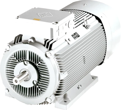
Booster (electric power)
Motor–generator set for DC voltage regulation, now obsolete.

A booster was a motor-generator set that regulated voltage in direct current power circuits. It became obsolete with the rise of alternating current and solid-state electronics. Different configurations were built for specific uses.
**Line booster** In the era of DC mains, voltage dropped along the line. A line booster corrected this. For example, if the mains supplied 110 V, houses near the power station got 110 V, but distant ones might get only 100 V. A line booster placed at a suitable point added voltage. It had a motor wired in parallel with the mains and a generator in series. The motor ran on the reduced 100 V, and the generator added 10 V to bring it back to 110 V. This system was inefficient and was replaced by AC mains, which allowed high-voltage distribution and transformer-based regulation.
**Milking booster** Power stations with DC mains often used large lead-acid batteries for load balancing. These batteries helped steam generators during peak demand and were recharged off-peak. If a single cell became faulty (sick), a milking booster gave it extra charge to restore it. The name came from “milking” the healthy cells to charge the faulty one. The booster’s motor connected across the whole battery, while its generator connected only across the bad cell. During discharge, the booster supplemented that cell’s output.
**Reversible booster** Before solid-state technology, reversible boosters controlled speed in DC electric locomotives. They could increase or decrease speed. The motor of the MG set connected in parallel with the 600 V supply and was mechanically linked, via a shaft with a heavy flywheel, to the generator. The generator was in series with the supply and the traction motors. By adjusting switches and resistors in the field circuit, its output could vary from +600 V through zero to −600 V. This let the generator voltage either oppose or add to the line voltage. The net output could be smoothly adjusted between zero and 1,200 V: with maximum opposing voltage, net output was zero; with zero generator voltage, net output was 600 V; with maximum supplementary voltage, net output was 1,200 V. To match 1,200 V, the locomotive used three 400 V traction motors in series. Later designs used two 600 V motors in series.
- Types
- line booster, milking booster, reversible booster
- Line booster voltage example
- 110 V mains, boosted from 100 V to 110 V
- Reversible booster supply voltage
- 600 V
- Reversible booster output range
- 0 to 1,200 V
- Reversible booster traction motor config
- three 400-volt motors in series, or two 600-volt motors in series
- Reversible booster power rating ratio
- half the rating of the traction motors
Lore & Background
In the days of direct current mains, voltage drop along the line was a problem so line boosters were used to correct it. A line booster consisted of a motor, connected in parallel with the mains, driving a generator, in series with the mains. For example, if the mains voltage was 110 V, houses near the power station would receive 110 volts but those remote might receive only 100 V; the line booster would be inserted at an appropriate point to boost the voltage. The motor ran at the depleted mains voltage of 100 V and the generator added another 10 V to restore the voltage to 110 V. This was an inefficient system and was made obsolete by the development of alternating current mains.
Again in the days of direct current mains, power stations often had large lead–acid batteries for load balancing. Sometimes one cell in the battery would become 'sick' (faulty, reduced capacity) and a 'milking booster' would be used to give it an additional charge and restore it to health. The milking booster was so-called because it 'milked' the healthy cells in the battery to give an extra charge to the faulty one. The motor side of the booster was connected across the whole battery but the generator side was connected only across the faulty cell. During discharge periods the booster supplemented the output of the faulty cell.
Before solid-state technology became available, reversible boosters were sometimes used for speed control in DC electric locomotives. The boosters were called reversible because they could either increase or decrease the speed of the locomotive. The motor of the MG set was connected in parallel with the supply, usually at 600 volts, and was mechanically coupled, via a shaft with a heavy flywheel, to the generator. The generator was connected in series with the supply and the traction motors, and its output could be varied from +600 volts, through zero, to −600 volts by adjusting switches and resistors in the field circuit. This allowed the generator voltage to either oppose, or supplement, the line voltage.
Reader's Guide
The reversible booster was significant for its efficiency in weight and cost compared to the Ward Leonard system. When the locomotive was working at full power, half the energy came through the MG set and the other half came directly from the supply, meaning the power rating of the MG set needed to be only half the rating of the traction motors. This system was used in the design of British Rail classes 70, 71 and 74 (Class 73 does not utilise booster equipment). If the power supply to the locomotive was interrupted (e.g., because of a gap in the third rail at a junction) the flywheel would power the MG set for a short period to bridge the gap, during which the motor of the MG set would temporarily run as a generator. The line booster was made obsolete by the development of alternating current mains, which allowed for high-voltage distribution and voltage regulation by transformers. The milking booster addressed the specific problem of sick cells in large lead–acid batteries used for load balancing. Additionally, when cathode ray tubes were standard for television receivers, a small 'booster' transformer could be added to raise the voltage applied to the filament slightly, increasing emission and restoring brightness, sometimes extending the life of the expensive CRT by years.
Did You Know?
- Line boosters were used to correct voltage drop along DC mains, for example boosting 100 V back to 110 V.
- Milking boosters were so named because they 'milked' healthy cells in a battery to give an extra charge to a faulty one.
- Reversible boosters could vary net output voltage smoothly between zero and 1,200 volts from a 600 V supply.
- The reversible booster system was used in British Rail classes 70, 71 and 74.
Taming Voltage Drop on DC Mains
In the era of direct current electrical distribution, a persistent engineering headache was the gradual loss of voltage as current traveled along overhead or underground feeders. A household close to the generating station might enjoy a full 110 volts, while one several miles down the line could see only 100 volts at its outlets. The line booster was the mechanical answer to this problem. It took the form of a motor-generator set in which the motor was wired in parallel with the mains, spinning at whatever depleted voltage the line happened to carry, while the generator was inserted in series with the line to inject the missing volts back into the circuit. In the 110-to-100-volt example, the generator simply added ten volts to restore the nominal level. The arrangement was functional but inherently inefficient, and its days ended when alternating current distribution matured. AC systems could step voltages up for long-haul transmission and step them down locally with transformers, eliminating the need for a rotating machine bolted into every sagging section of a DC feeder.
The Milking Booster and Battery Revival
Power stations of the DC era relied on large banks of lead-acid cells to smooth out demand peaks, discharging into the grid when steam generators could not respond quickly enough and recharging during quiet hours. Over time, individual cells would degrade, losing capacity and dragging down the performance of the entire bank. The milking booster was a targeted remedy for this single-cell failure. Its motor was connected across the full battery string, drawing power from all the healthy cells, while its generator was wired across only the one sick cell, feeding it an extra charge to coax it back toward full capacity. The name "milking" captured the process vividly: the healthy cells were, in effect, milked to sustain their weaker neighbor. During discharge cycles the booster also supplemented the output of the weakened cell so the bank could still deliver its rated power. It was a clever, if narrow, application of the motor-generator principle to keep an aging battery serviceable without replacing the entire array.
Reversible Boosters and Locomotive Speed Control
Before solid-state electronics offered electronic speed regulation, DC electric locomotives sometimes turned to a reversible booster for smooth control of traction-motor speed. The motor was wired in parallel with the 600-volt supply and linked, through a shaft fitted with a heavy flywheel, to the generator, which sat in series with the traction motors. By adjusting switches and resistors in the generator's field circuit, its output could be swept from plus 600 volts, through zero, to minus 600 volts, letting the net voltage seen by the motors range from zero up to 1,200 volts. A locomotive might carry three 400-volt motors in series, or later two 600-volt units. At full power, half the energy flowed through the booster and half directly from the line, meaning the MG set needed only half the rating of the traction motors—a significant saving in weight and cost over the Ward Leonard arrangement. The flywheel also bridged brief supply interruptions, such as gaps in a third rail at a junction. British Rail classes 70, 71, and 74 employed this system, while class 73 did not.
The Booster in the Living Room
The concept of boosting voltage did not remain confined to power stations and railways; it found a quiet second life inside the cathode-ray television sets that dominated living rooms for decades. After years of continuous service, a CRT would gradually dim as the electron-emitting filaments in its gun assembly aged and lost emission capability. Rather than replacing the entire expensive tube, a technician could add a small booster transformer to the set. This device nudged the filament voltage slightly higher, increasing electron emission and restoring the picture to acceptable brightness. In many cases the intervention bought the tube several more years of useful service, making it far more economical than a full replacement. Though the booster transformer in a television was a tiny component compared to the heavy motor-generator sets of the DC grid, it shared the same underlying logic: a modest, targeted increase in voltage to compensate for a shortfall elsewhere in the circuit.
Frequently Asked Questions
What is a booster (electric power)?
A booster is a motor-generator set that was used to regulate voltage in direct-current power circuits. It has been rendered obsolete by the widespread shift to alternating-current systems and the advent of solid-state electronic controls.
How did a line booster compensate for voltage drop along a DC mains line?
It employed a motor wired in parallel with the mains and a generator connected in series to inject extra voltage at a chosen tap point. For example, it could raise a sagging 100-volt reading back up to the intended 110 volts for distant consumers.
What was a reversible booster and what voltage range did it cover?
A reversible booster was designed for traction service, accepting a 600-volt supply and delivering an adjustable output from zero up to 1,200 volts. Its power rating was set at roughly half that of the traction motor set it served.
How were traction motors configured alongside a reversible booster?
The traction motors could be arranged as three 400-volt units in series or as two 600-volt units in series. In either configuration the booster's rating was about half the combined rating of those traction motors.
What types of boosters existed in DC power systems?
The principal configurations were the line booster, the milking booster, and the reversible booster. Each was tailored to a particular application, from correcting line drop to powering traction motors.
More in Electric Motors 1-24
Spotted an error? Know more?
Reader corrections go straight into our review queue. Suggest an edit · How this site is sourced