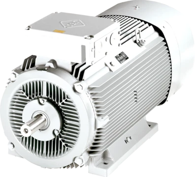
Armature-controlled DC motor
A DC motor controlled via armature coils with constant stator flux.

An armature-controlled DC motor is a type of direct current motor that relies solely on its armature coils for operation, using a permanent magnet to maintain a constant stator flux. This design is the most common control method for DC motors, making them popular in applications such as robotics, tape drives, and machinery.
In a standard DC motor, the stator (with field windings) and the rotor (or armature, with its own windings) both receive current, generating magnetic flux that interacts to produce rotation. For armature control, the stator flux must stay constant, which is achieved either by keeping the stator voltage steady or by replacing the stator coils with a permanent magnet—creating a permanent magnet DC motor driven only by the armature.
The motor’s torque is given by \( T = K_{\phi} \Phi I \), where \( K_{\phi} \) depends on the stator flux \( \Phi \). When the flux is constant, this simplifies to \( T = K' I \), meaning torque is directly proportional to armature current. Additionally, the motor has inherent negative feedback, so at steady state, speed \( \omega \) is proportional to the input voltage \( V_a \).
These features, along with the lower cost of a permanent magnet motor (since only the rotor coils need winding), explain why armature-controlled motors are widely used. However, a major drawback is the large current flow during transients. For example, at startup, speed is zero, so the back electromotive force (\( E_b = K_{\phi} \phi \omega \)) is also zero. The armature current then becomes \( I = (V - E_b) / R_a \), which can be very high, increasing heat and risking insulation damage.
- Torque equation
- T = K_φ Φ I
- Torque with constant flux
- T = K' I
- Back emf equation
- E_b = K_φ φ ω
- Armature current equation
- I = (V - E_b) / R_a
- Rotor gain
- K_a = 1 / R_a
- Electrical time constant
- τ_a = L / R_a
Lore & Background
The armature-controlled DC motor is a type of separately excited DC motor, where control is achieved by varying the armature voltage while keeping the stator flux constant. To maintain constant stator flux, either the stator voltage is kept constant or the stator coils are replaced by a permanent magnet; in the latter case, the motor is called a permanent magnet DC motor and is driven by the armature coils only. The motor consists of a rotor (armature) and a stator, with the stator providing a constant magnetic field.
The operation is governed by linearized equations that simplify the magnetic field effects to a flux term Φ and a term K_φ describing the effect of the stator field on the rotor. Torque is proportional to armature current when field flux is constant, and the motor has an intrinsic negative feedback structure, making steady-state speed proportional to the reference input voltage. However, a major disadvantage is the flow of large currents during transients, such as at startup when speed is zero and back EMF is zero, leading to high armature current that can cause heating and damage insulation.
Reader's Guide
The armature-controlled DC motor is significant because it is the most common control technique for DC motors, widely used in control applications such as robotics, tape drives, and machines. Its widespread use stems from two key facts: the motor's torque is proportional to armature current when field flux is constant, and at steady state, speed is proportional to the reference input voltage. Additionally, a permanent magnet version is cheaper than a standard DC motor because only the rotor coils need to be wound. However, the technique has disadvantages, primarily the flow of large currents during transients, which can cause increased heating and damage to insulation. The motor's behavior is described by linearized equations involving torque, back EMF, and armature current, with parameters such as rotor gain and electrical time constant defined for transfer function analysis.
Did You Know?
- An armature-controlled DC motor uses a permanent magnet driven by the armature coils only.
- Large currents flow during transients, such as at startup, because back EMF is zero.
How Torque Is Generated Through Field Misalignment
At the heart of any DC motor lies a fundamental electromagnetic principle: torque emerges whenever the magnetic fields of the rotor and stator are held in a state of deliberate misalignment. In a brushless configuration, direct current is routed through stator windings by an electronic controller, which carefully modulates both the phase and amplitude of the current pulses. This produces magnetic fields that effectively rotate in space, and a permanent magnet rotor follows these fields, generating continuous rotational force. The controller's ability to adjust the timing and magnitude of each pulse is what gives the operator precise, nearly instantaneous command over both speed and torque. Unlike the older brushed design where a mechanical commutator handled the switching, here the entire process of keeping the fields misaligned is managed electronically, allowing the motor to sustain smooth, unidirectional torque without the need for any physical sliding contacts on the rotating assembly.
Why the Mechanical Commutator Became a Liability
For much of the twentieth century, brushed DC motors dominated industrial applications, relying on a rotary switch mounted on the motor shaft to route current to successive windings. The system worked, but it carried a constellation of drawbacks that gradually eroded its relevance. The soft graphite brushes pressed against the rotating commutator segments generated friction that consumed meaningful power, particularly in low-output machines. That same friction wore the brushes down, shedding particulate dust and eventually demanding replacement—a fatal flaw for sealed environments like hard disk drives or any application requiring maintenance-free operation. The sliding contact introduced a voltage drop known as brush drop, wasting energy in the circuit. Perhaps most dangerously, the abrupt switching of current through inductive windings produced sparks at the commutator contacts, creating fire risks in explosive atmospheres and generating electromagnetic interference that disrupted nearby microelectronics. Over the past century, high-power brushed motors yielded to AC synchronous machines, and even in low-power niches these persistent weaknesses continue to constrain their use.
Solid-State Electronics Replace the Mechanical Switch
The breakthrough that made brushless DC motors practical arrived with the maturation of solid-state electronics in the 1960s. In this architecture, an electronic sensor continuously monitors the angular position of the rotor, and that information drives semiconductor switches—typically transistors—that route current through the stator windings at precisely the right moment. Depending on the design, the controller either reverses the direction of current in a given winding or simply cuts it off, ensuring the resulting magnetic field always pulls the rotor forward in a single direction. Because no sliding electrical contacts exist, the friction and wear that plagued brushed designs vanish entirely; the motor's operational lifespan is now governed solely by the endurance of its bearings. The permanent magnets sit on the rotor while the windings remain fixed in the stator, eliminating the challenge of delivering current to a spinning armature. The trade-off is that the control electronics must be more complex, potentially less rugged, and more expensive than the simple brush-and-commutator assembly they replace.
Performance Gains and the Spread Into Everyday Machines
Brushless DC motors deliver a suite of performance characteristics that have made them the preferred choice across a remarkably wide range of applications. Their high power-to-weight ratio, superior efficiency, and near-instantaneous speed and torque control outperform brushed counterparts in almost every metric. The elimination of brush erosion and commutator sparks also means reduced noise, lower electromagnetic interference, and a longer service life. Because the windings are anchored to the stationary housing rather than the spinning rotor, they are immune to centrifugal stress and can be cooled by conduction through the frame, removing the need for internal airflow. Construction variants include outrunner, inrunner, and axial geometries, with some designs employing neodymium magnets for additional field strength. These attributes have carried brushless motors into computer peripherals such as disk drives and printers, hand-held power tools, model aircraft, automobiles, and even modern washing machines, where a direct-drive brushless motor has replaced the rubber belt and gearbox assemblies of earlier generations.
Frequently Asked Questions
Who is Armature-controlled DC motor?
It is a direct-current motor whose stator field is locked in place by a permanent magnet, so every active control action is applied exclusively to the rotor's armature windings. This makes it the simplest and most widely deployed configuration among DC motor control schemes.
What are Armature-controlled DC motor's powers and role?
Because stator flux never varies, its output torque scales linearly with armature current (T = K′I), and its rotational speed is set directly by the applied voltage minus the generated back-EMF. That clean one-to-one voltage-to-speed relationship is what makes it a go-to choice in robotics, tape drives, and general industrial machinery.
Why is Armature-controlled DC motor important?
It represents the most common control topology for DC machines, giving engineers a straightforward linear torque-current relationship without needing a separate field-power supply. Its predictable single-axis dynamics—summarised by the electrical time constant τ_a = L/R_a and rotor gain K_a = 1/R_a—made it a workhorse across decades of industrial and hobbyist robotics.
What is Armature-controlled DC motor's signature weakness?
With the stator flux permanently fixed, there is no second control axis to reshape the speed-torque curve the way a separately excited motor can. This single-axis limitation constrains flexibility in high-performance or very wide-speed-range applications.
More in Electric Motors 1-24
Spotted an error? Know more?
Reader corrections go straight into our review queue. Suggest an edit · How this site is sourced