Impedance analyzer
Measures complex electrical impedance as a function of test frequency.

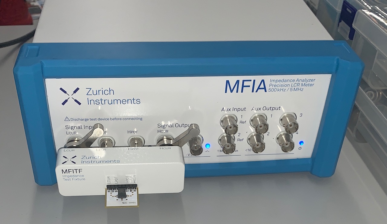
An impedance analyzer is an electronic instrument that measures complex electrical impedance across a range of test frequencies. Impedance itself is a key parameter for characterizing electronic components, circuits, and the materials from which components are made. It can also be applied to materials with dielectric properties, such as biological tissue, food products, and geological samples. These analyzers are built in three distinct hardware configurations, which together cover frequencies from ultra-low to ultra-high and can measure impedances spanning from micro-ohms to tera-ohms.
During operation, an impedance analyzer applies a voltage and current to a device under test while varying the measurement frequency, then performs a phase-sensitive measurement of both signals. Key performance specifications include the frequency range, impedance range, absolute impedance accuracy, and phase angle accuracy. Additional specifications cover the ability to apply voltage or current bias during measurement, as well as measurement speed. These instruments typically achieve high accuracy—for example, a basic accuracy of up to 0.05%—with a frequency range from microhertz to gigahertz. Impedance values can span many orders of magnitude, from micro-ohms to tera-ohms, while phase angle accuracy is on the order of ten millidegrees. Measured quantities include absolute impedance, its real and imaginary components, and the phase angle between voltage and current. Derived parameters such as conductance, inductance, and capacitance are calculated from a replacement circuit model and then displayed.
LCR meters also measure impedance, offering similar accuracy but a narrower frequency range. Their measurement frequencies are typically fixed rather than swept, and results cannot be displayed graphically. A separate instrument, the vector network analyzer (VNA), measures impedance as well, but at much higher frequencies and with significantly lower accuracy than an impedance analyzer.
Most impedance analyzers include a reactance chart that displays capacitive reactance (XC) and inductive reactance (XL) values for a given frequency. The instrument’s accuracy is overlaid on this chart, enabling users to quickly determine the expected accuracy for a specific frequency and reactance value.
- Basic accuracy
- up to 0.05%
- Frequency range
- μHz to GHz
- Impedance range
- μΩ to TΩ
- Phase angle accuracy
- 10 millidegree
Lore & Background
Impedance analyzers come in three distinct hardware implementations, which together can probe from ultra low frequency to ultra high frequency and measure impedances from μΩ to TΩ. Operation involves phase-sensitive measurement of current and voltage applied to a device under test while the measurement frequency is varied. Key specifications include frequency range, impedance range, absolute impedance accuracy, and phase angle accuracy, as well as the ability to apply voltage and current bias and measurement speed. Measured values include absolute impedance, real and imaginary parts, and phase angle; model-derived parameters such as conductance, inductance, and capacitance are calculated based on a replacement circuit model. Most impedance analyzers include a reactance chart showing capacitive and inductive reactance values for a given frequency, with instrument accuracy transposed on the chart to allow quick assessment of expected accuracy.
Reader's Guide
Impedance analyzers are distinguished from LCR meters, which provide similar accuracy but generally have a lower, fixed frequency range and cannot display measurements graphically. A fourth implementation, the vector network analyzer (VNA), is considered a distinct instrument; VNAs measure impedance at much higher frequencies but with much lower accuracy compared to impedance analyzers. The ability to sweep frequency and display results graphically makes impedance analyzers essential for detailed characterization of components and materials across a wide frequency and impedance range. Their high accuracy—up to 0.05% basic accuracy and phase angle accuracy in the range of 10 millidegree—supports precise analysis of electronic circuits and dielectric materials. The inclusion of a reactance chart aids users in quickly determining measurement accuracy for specific frequency and reactance combinations.
Did You Know?
- Impedance analyzers can measure impedances from μΩ to TΩ.
- They offer basic accuracy up to 0.05% and phase angle accuracy in the range of 10 millidegree.
- Three distinct hardware implementations allow probing from ultra low frequency to ultra high frequency.
Purpose and Breadth of Application
In the landscape of electronic test equipment, the impedance analyzer stands out as an instrument purpose-built to capture complex electrical impedance values while sweeping through a range of test frequencies. Impedance serves as a foundational parameter for characterizing electronic components, complete circuits, and the raw materials from which those components are fabricated. The instrument's utility, however, extends well beyond the electronics workshop. Because it can probe how any substance responds to alternating electrical signals, impedance analysis finds application in characterizing materials that exhibit dielectric behavior. This includes biological tissue, foodstuffs, and geological samples, making the analyzer a versatile bridge between electrical engineering and disciplines such as biology, food science, and geology. By observing how impedance shifts across frequency, researchers gain insight into the internal structure and physical properties of the material under investigation.
Three Hardware Architectures and Measurement Span
Rather than existing as a single monolithic device, the impedance analyzer is realized in three distinct hardware implementations. Collectively, these three architectures allow the user to probe from ultra low frequency all the way to ultra high frequency, and to resolve impedances spanning from micro-ohms up to tera-ohms. This extraordinary dynamic range means the instrument family can handle conditions approaching a near-short-circuit as easily as a near-open-circuit. The frequency span stretches from microhertz to gigahertz, while impedance values can cover many orders of magnitude. Defining specifications for any given unit include its frequency range, impedance range, absolute impedance accuracy, and phase angle accuracy. Additional performance criteria encompass the capability to apply voltage bias and current bias during a measurement, as well as the speed at which a full sweep can be completed.
Operational Principles and Precision Levels
At its operational core, an impedance analyzer performs a phase-sensitive measurement of both the current and voltage applied to a device under test while the measurement frequency is varied across the desired span. This simultaneous, phase-aware approach is what elevates the instrument above simpler single-point testers. Typical accuracy figures are striking: basic impedance accuracy can reach as tight as 0.05 percent, and phase angle accuracy can be as fine as ten millidegrees. The instrument reports absolute impedance, the real and imaginary components, and the phase relationship between voltage and current. It can also derive model-based parameters such as conductance, inductance, and capacitance by fitting the measurement to a replacement circuit model and displaying those calculated values. The combination of frequency sweeping, sub-percent precision, and model-based parameter extraction makes the analyzer far more powerful than a static measurement device.
Position Among Related Instruments
The impedance analyzer occupies a specific and well-defined niche among related test equipment. LCR meters also provide impedance measurement functionality and can achieve comparable accuracy, but they typically operate at a lower frequency range. A critical distinction is that LCR meters generally use a fixed measurement frequency rather than sweeping it, and their results cannot be displayed graphically across a frequency span. At the opposite end of the spectrum sits the vector network analyzer, which is best regarded as a distinct instrument class. While VNAs also measure impedance, they typically operate at much higher frequencies and with considerably lower accuracy than dedicated impedance analyzers. Most impedance analyzers additionally ship with a reactance chart that plots capacitive and inductive reactance values for a given frequency, with the instrument's accuracy transposed onto the chart so users can quickly gauge the expected precision for any particular frequency and reactance combination.
Gallery
More in Radio Electronics 1-24
Spotted an error? Know more?
Reader corrections go straight into our review queue. Suggest an edit · How this site is sourced