Absorption wavemeter
Simple resonant instrument for measuring radio wave frequency.

An absorption wavemeter is a basic electronic tool for determining the frequency of radio waves. This technique for measuring frequency was common from the early days of radio in the 20th century through the 1970s, after which affordable frequency counters—offering much better precision—largely replaced it.
The device works with an adjustable resonant circuit that is marked with a frequency scale, along with a meter that shows voltage or current in the circuit. When the circuit is tuned to match an unknown frequency, it absorbs energy from that signal, causing a noticeable dip on the meter. The frequency is then read from the dial.
Wavemeters suit measurements where high accuracy is not critical, such as verifying that a radio transmitter stays within its proper frequency band or detecting harmonics in its output. Many amateur radio operators keep one as a straightforward way to check their transmission frequency. Similar devices can be built to detect mobile phones. A dip meter can serve as an alternative.
There are two main types: transmission wavemeters, which have input and output ports and sit directly in the signal path, and absorption wavemeters, which couple loosely to the radio frequency source and draw energy from it.
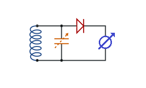
For HF and VHF, the simplest form uses a variable capacitor connected across a coil. A diode is attached to one terminal of this LC circuit, and a ceramic decoupling capacitor connects between the diode’s other end and the remaining LC terminal. A galvanometer is wired across the decoupling capacitor’s terminals. This setup responds to strong radio sources at the resonant frequency of the LC circuit. When exposed to an RF field at that frequency, a DC voltage appears at the output terminals. The coil is usually placed outside the unit’s case so it can be brought near the object under test.
At UHF and SHF, lumped components cannot be used for the tuned circuit. Instead, methods like stripline or resonant cavities are employed. One design for UHF and SHF uses a resonant quarter-wave (λ/4) rod with adjustable length. Another design for X-band (10 GHz) uses a resonant cavity whose length can be changed. For UHF, Lecher transmission lines are an alternative, allowing rough frequency measurement of a transmitter.
- Frequency range example
- 8.2 GHz to 12.4 GHz (HP Model 532A)
- Typical use period
- early 20th century until the 1970s
Lore & Background
A wavemeter consists of an adjustable resonant circuit calibrated in frequency, with a meter or other means to measure the voltage or current in the circuit. When adjusted to resonance with the unknown frequency, the resonant circuit absorbs energy, which is indicated by a dip on the meter. Then the frequency can be read from the dial. There are two categories of wavemeters: transmission wavemeters, which have an input and an output port and are inserted into the signal path, or absorption wavemeters, which are loosely coupled to the radio frequency source and absorb energy from it.
At HF and VHF, the most simple form of the device is a variable capacitor with a coil wired across its terminals. Attached to one of the terminals of the LC circuit is a diode, then between the end of the diode not wired to the LC circuit and the terminal of the LC circuit not bearing the diode is wired a ceramic decoupling capacitor. Finally a galvanometer is wired to the terminals of the decoupling capacitor. The device will be sensitive to strong sources of radio waves at the frequency at which the LC circuit is resonant. The coil is often outside the case of the unit so it can be brought close to the object being probed.
At UHF and SHF, it is not possible to use lumped components for the tuned circuit. Instead methods such as stripline or resonant cavities are used. One design for ultra high frequencies (UHF) and super high frequencies (SHF) is a resonant λ/4 (quarter wave) rod which can vary in length. Another design for X-band (10 GHz) is a resonant cavity which can be changed in length. As an alternative for UHF, Lecher transmission lines can be used.
Reader's Guide
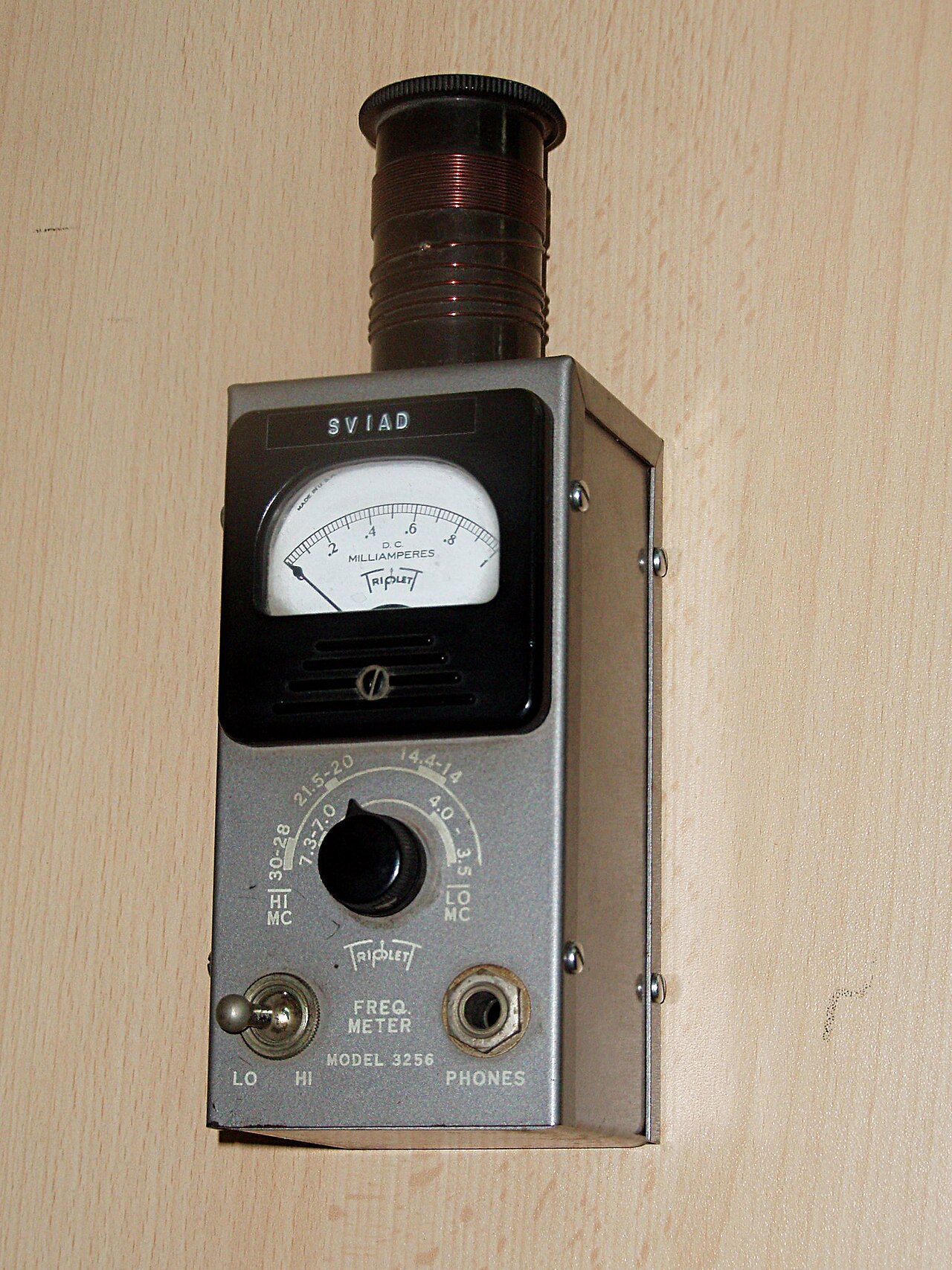
Absorption wavemeters were a standard tool for frequency measurement from the early days of radio until the 1970s, when inexpensive frequency counters with far greater accuracy made them largely obsolete. They are used for frequency measurements that do not require high accuracy, such as checking that a radio transmitter is operating within its correct frequency band, or checking for harmonics in the output. Many radio amateurs keep them as a simple way to check their output frequency. Similar devices can be made for detection of mobile phones. As an alternative, a dip meter can be used. The instrument's simplicity—an adjustable resonant circuit with a meter—made it accessible and practical for field use. Examples include the Triplet 3256 wavemeter for the high frequency band and the HP Model 532A frequency meter for measuring microwave frequencies in the range between 8.2 GHz to 12.4 GHz with waveguide flanges. While no longer a primary measurement tool, the absorption wavemeter remains a useful backup or educational device for understanding resonance and frequency measurement principles.
Did You Know?
- An absorption wavemeter is loosely coupled to the radio frequency source and absorbs energy from it.
- The HP Model 532A frequency meter measures microwave frequencies between 8.2 GHz and 12.4 GHz with waveguide flanges.
- At UHF and SHF, resonant cavities or quarter-wave rods are used instead of lumped components.
- A wavemeter indicates resonance by a dip on the meter when the circuit absorbs energy.
A Century of Service and the Arrival of a Better Tool
The absorption wavemeter occupied a unique place in the history of radio measurement. From the very dawn of wireless communication in the early 1900s, this simple electronic instrument served as a go-to device for determining the frequency of radio waves. For roughly seven decades it was a staple in workshops, laboratories, and amateur stations worldwide. Its reign came to an end in the 1970s, when manufacturers began producing frequency counters that were both inexpensive and dramatically more accurate. The wavemeter did not vanish overnight, but it was pushed into the role of a rough-checking tool, no longer the primary means of frequency determination. What made the device so enduring was its simplicity: it required no complex electronics, no digital processing, and no calibration beyond the basic resonant circuit. For a generation of engineers and hobbyists, the gentle dip on an analog meter was all the confirmation they needed that a signal sat at the right frequency. Its obsolescence marked the quiet retirement of an era in which radio measurement was still a largely analog, hands-on craft.
How the Dip Tells the Frequency
At its core, an absorption wavemeter is built around an adjustable resonant circuit that has been calibrated against a frequency scale. The user tunes this circuit until it matches the unknown signal, and at that moment the circuit absorbs energy from the source. This absorption registers as a visible dip on a meter or other voltage-and-current indicator, and the corresponding value on the dial gives the frequency. The device belongs to one of two broad families of wavemeters. Transmission wavemeters feature both an input and an output port, so they are physically inserted into the signal path. Absorption wavemeters, by contrast, are only loosely coupled to the radio-frequency source and draw energy from the field without being wired into the circuit. This looser coupling is what makes them particularly convenient for quick, non-intrusive checks. The underlying physics is straightforward: when the resonant frequency of the LC circuit aligns with the incoming wave, maximum energy transfer occurs, and the meter's needle drops. Reading the dial at that point yields the frequency.
A Tool for the Working Radio Operator
The absorption wavemeter was never intended for precision metrology. Its sweet spot was the kind of frequency check that a practical radio operator needs: confirming that a transmitter is radiating within its assigned band, or spotting unwanted harmonics creeping into the output. Because of this, it became a familiar companion in amateur radio stations, where hobbyists valued it as a quick, low-effort way to verify their output frequency before going on the air. The same loosely coupled principle can be adapted to detect signals from mobile phones, extending the device's utility beyond traditional radio. For those who want a slightly different approach, a dip meter serves a similar purpose, and the grid dip oscillator occupies a related niche in the same family of instruments. What unites all of these tools is a shared philosophy: when you do not need the last decimal place of accuracy, a simple resonant circuit and a sensitive meter are all you need to get a reliable, immediate answer.
From Coils to Cavities: Adapting to Higher Frequencies
Building an absorption wavemeter for the HF and VHF ranges is remarkably straightforward. The classic design pairs a variable capacitor with a coil wired across its terminals, adds a diode to one terminal, inserts a ceramic decoupling capacitor, and connects a galvanometer to read the resulting DC voltage. The resonant frequency follows the familiar relationship of one over two-pi times the square root of inductance times capacitance. When the device is held near a strong RF source at that resonant frequency, a DC voltage appears across the diode terminals and the galvanometer swings. The coil is often mounted outside the enclosure so the operator can bring it close to the object under test. At UHF and SHF frequencies, however, lumped components no longer work. Designers turn instead to striplines, resonant cavities, or a variable-length quarter-wave rod. For X-band work around ten gigahertz, a tunable resonant cavity is the go-to solution, while Lecher transmission lines offer yet another alternative for rough UHF measurements.
Gallery
More in Radio Electronics 1-24
Spotted an error? Know more?
Reader corrections go straight into our review queue. Suggest an edit · How this site is sourced