Balun
An electrical device interfacing balanced and unbalanced lines.

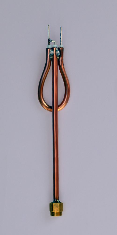
A balun (short for "balanced to unbalanced," though now also understood as "balancing unit") is an electrical device that connects balanced and unbalanced transmission lines without disrupting the impedance of either line. Baluns come in various forms; some also transform impedances, but this is not required. While transformer-type baluns often use magnetic coupling, this is also optional. Common-mode chokes serve as baluns as well, functioning by eliminating common-mode signals rather than simply rejecting them.
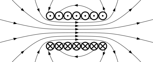
**Classical transformer type** In classical transformer baluns, two electrically separate wire coils are wound around a core. This separation between input and output windings allows these baluns to connect circuits with different ground voltages, preventing ground loops—hence they are often called isolation transformers. Also known as voltage baluns, they have a primary winding that receives the input signal and a secondary winding that delivers the converted signal. The core may be air, a magnetically neutral material like porcelain, or a magnetic conductor such as ferrite (common in modern high-frequency baluns) or soft iron (used in early telegraphy). When current in the primary coil reverses, the magnetic field in the core collapses, inducing an electric field in the secondary winding. The ratio of turns between windings and the efficiency of magnetic coupling determine the output voltage-to-current ratio and total power. In an ideal transformer, power remains constant, though real transformers lose some energy to core heating, winding resistance, and imperfect magnetic coupling.
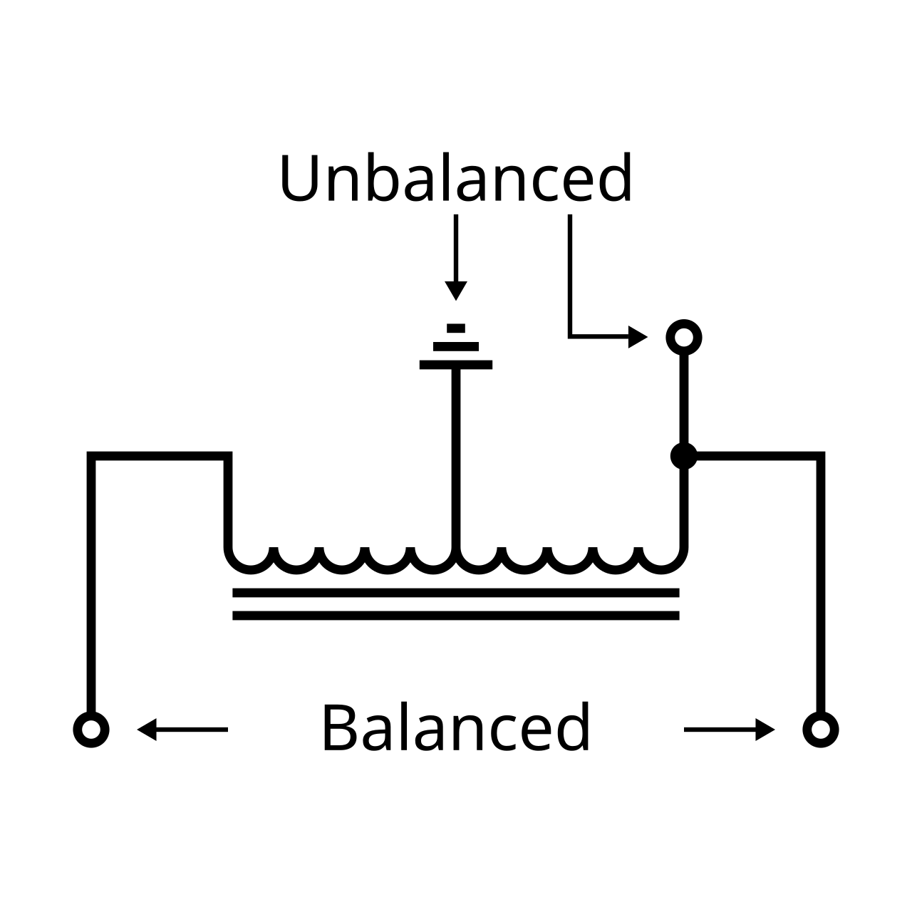
**Autotransformer type** An autotransformer balun uses a single coil (or multiple electrically connected coils) wound around a core. It can also be made by cross-wiring the primary and secondary of an ordinary transformer. These are also called voltage baluns because they produce balanced output voltage but not necessarily balanced current. The single winding must have at least one tap between its ends. Input current magnetizes the entire core; when the current changes, the collapsing magnetic field induces current throughout the coil. Connections to different parts of the coil yield higher or lower voltages depending on the tapped length.
- Types
- Classical transformer type, autotransformer type, transmission-line transformer type, planar and Marchand baluns
- Frequency range
- Up to at least 100 GHz for planar types
- Inventor of marchand balun
- Nathan Marchand
- Year of guanella transformer
- 1944
- Year of marchand proposal
- 1944
Lore & Background
The classical transformer type balun uses two electrically separate windings of wire coils around a core, allowing connection of circuits with different ground-level voltages and preventing ground loops; these are often called isolation transformers. The autotransformer balun has only one coil or multiple electrically connected coils wound around a core, providing a DC path to ground from every terminal, which can be advantageous for draining static charge from outdoor antennas. The transmission-line transformer type, sometimes called a current balun, ensures equal current on both sides of its output and can combine capacitive coupling with magnetic coupling to operate at significantly higher frequencies, up to 8 GHz and above. For even higher frequencies, planar baluns based on Nathan Marchand's 1944 conversion transformer work by exciting a mode in a ground plane or shield, allowing extraction of positive and negative signal pairs, and have been adapted for use in MMICs and RFICs at frequencies up to at least 100 GHz.
Reader's Guide
Baluns find extensive application in modern communications, particularly in realising frequency conversion mixers that make cellular phone and data transmission networks possible. They are also used to send E1 signals. The device's ability to achieve compatibility between balanced and unbalanced systems is fundamental to many radio and telecommunications interfaces. The self-resonance of a balun, arising from the combination of self-inductance and self-capacitance in its windings, limits its operating frequency; design considerations aim to place the resonant frequency well above the operating frequency. An RF choke can serve as an alternative to a 1:1 current balun, for example by passing coaxial cable through a ferrite toroid near the feed point of a balanced antenna, achieving the same effect as a Guanella-type balun.
Did You Know?
- A balun can take many forms and may include devices that also transform impedances but need not do so.
- Common-mode chokes used as baluns work by eliminating, rather than rejecting, common mode signals.
- Autotransformer baluns provide a DC path to ground from every terminal, which can drain static charge from outdoor antennas.
- Transmission line transformer baluns can operate to 8 GHz and above by combining capacitive coupling with magnetic coupling.
Name, Purpose & Core Function
A balun is an electrical device whose name originally spelled out the phrase "balanced to unbalanced," though contemporary usage instead derives the term from "balancing unit." Its core purpose is to bridge a balanced line with an unbalanced one while preserving the impedance characteristics of both sides of the connection. This function is essential wherever two fundamentally different line topologies must share a signal path. A balun is not a single fixed component; it can assume many physical forms, and while some designs also perform impedance transformation, that is an optional secondary role rather than a defining requirement. Certain implementations exploit magnetic coupling, as in transformer-based architectures, while others accomplish the same interfacing goal through entirely different physical mechanisms. Common-mode chokes, for example, qualify as baluns by eliminating common-mode signals outright rather than merely rejecting them, illustrating that the category encompasses a range of operational philosophies united by a single functional objective.
Transformer & Autotransformer Architectures
The classical transformer balun employs two electrically isolated wire windings wrapped around a shared core. This isolation is its signature advantage: because the input and output coils share no direct electrical connection, the device can link circuits whose ground potentials differ, effectively acting as an isolation transformer in environments where ground loops are a persistent hazard. The incoming signal drives the primary winding, generating a magnetic field in the core; when that current reverses, the collapsing field induces a converted signal in the secondary. Core materials have evolved from air and porcelain in early telegraphic equipment to soft iron and, in modern high-frequency designs, ferrite. The autotransformer variant, by contrast, uses a single winding with a tap point between its two ends. This topology inherently creates a DC path to ground from every terminal, a practical benefit for outdoor antennas where static charge accumulates and needs a safe drainage route. Both families are sometimes labeled voltage baluns because they deliver balanced output voltage, though balanced current is not guaranteed.
Transmission-Line Transformers & the Frequency Ceiling
Transmission-line baluns, frequently called current baluns or ununs, guarantee equal current on both sides of the output rather than equal voltage. They represent straightforward forms of transmission-line transformers and can be hybridized with magnetic coupling to yield devices with remarkably wideband performance. The Guanella transmission-line transformer, described in 1944, is a well-known example often paired with a balun to serve as an impedance-matching network, splitting a 75-ohm line into two parallel 150-ohm branches that are then combined in series for 300 ohms. Classic magnetic transformers, however, hit a hard frequency wall: the permeability of their core material degrades rapidly above the megahertz range, capping useful operation near one gigahertz. Microwave systems spanning one to one hundred gigahertz—needed for mixers, push-pull amplifiers, and differential analog-to-digital converter interfaces—demand alternative approaches. Wirewound transmission-line pairs that blend capacitive and magnetic coupling push the operational ceiling to eight gigahertz and beyond.
Planar & Marchand Baluns for Extreme Frequencies
At the highest operating frequencies, magnetic loading simply ceases to be effective, forcing engineers toward fundamentally different circuit topologies. In 1944, Nathan Marchand proposed a conversion transformer capable of maintaining performance across a one-to-three bandwidth ratio. That basic circuit has since been extensively adapted and modified for integration into planar structures such as monolithic microwave integrated circuits and radio-frequency integrated circuits, extending operational capability to at least one hundred gigahertz—a regime where traditional wound-core designs are wholly impractical. The Marchand circuit's ability to sustain meaningful bandwidth without depending on magnetic materials makes it indispensable for modern high-speed electronics, including the differential interfaces that link analog and digital signal-processing stages. Tracing the lineage from soft-iron cores in telegraphy, through ferrite toroids and wirewound transmission lines, to etched planar geometries reveals a continuous engineering thread driven by the relentless demand to push balun operation into ever-higher frequency territory.
Gallery


More in Radio Electronics 1-24
Spotted an error? Know more?
Reader corrections go straight into our review queue. Suggest an edit · How this site is sourced