
Arc converter
Early continuous-wave radio transmitter using an electric arc.

The arc converter, also called the arc transmitter or Poulsen arc, was a type of spark transmitter used in early wireless telegraphy. It employed an electric arc to convert direct current electricity into radio frequency alternating current, and was one of the first transmitters capable of generating continuous sinusoidal waves. It was used as a radio transmitter from 1903 until the 1920s, when vacuum tube transmitters replaced it.
- Inventor
- Valdemar Poulsen
- Year of invention
- 1903
- Frequency range
- a few kilohertz to a few tens of kilohertz
- Notable user
- U.S. Navy
- Peak power example
- 1 megawatt
- Replaced by
- vacuum tube transmitters
- Ieee milestone
- yes
Lore & Background
The arc converter was developed by Danish engineer Valdemar Poulsen in 1903. Earlier work by Elihu Thomson in 1892 and William Duddell in 1900 had explored generating high-frequency currents from direct current using an electric arc. Poulsen improved efficiency by having the arc burn in hydrogen vapor instead of air, achieving frequencies up to 150 kHz. By 1903, Poulsen and Peder Oluf Pedersen had developed a workable continuous wave radio system for telephony and telegraphy. A syndicate formed in Copenhagen, and a station was established in Lyngby in 1906. Patent rights were acquired by various companies, including the Amalgamated Radio Telegraph Company and C. Lorenz AG. In 1909, Cyril Frank Elwell formed the Poulsen Wireless Telephone and Telegraph Company, and by 1910 stations in Sacramento and Stockton, California were in communication. The U.S. Navy ordered a 100 kilowatt arc in 1913. By 1912, the Federal Telegraph Company had established thirteen stations on the west coast plus Chicago, Kansas City and Fort Worth. In 1922, the Bureau of Standards stated that the arc was the most widely used transmitting apparatus for high-power, long-distance work, responsible for 80 percent of all energy radiated into space for radio purposes.
Reader's Guide
The arc converter was significant because it produced continuous (undamped) waves on a single frequency, unlike earlier spark-gap transmitters that generated damped waves wasting power and causing interference. This made it one of the first technologies used to transmit sound (amplitude modulation) by radio. The Poulsen arc converter had a tuned circuit connected across the arc, with the arc burning in hydrogen gas between a carbon cathode and a water-cooled copper anode, and a magnetic field applied. It was most successful in the frequency range of a few kilohertz to a few tens of kilohertz. Keying was complex: normal on-off keying could not be used because the arc took time to stabilize. Instead, frequency-shift keying (compensation-wave method) was employed, where the key altered the frequency by one to five percent. This method used a lot of spectrum bandwidth and was prohibited around 1921 by the Preliminary International Communications Conference. Later uniwave methods included the ignition method (starting and stopping the arc) and the absorption method (switching the arc between the antenna and a dummy load). The arc converter is listed as an IEEE Milestone as a historic achievement in electrical engineering.
Did You Know?
- The arc converter was one of the first transmitters that could generate continuous sinusoidal waves.
- The U.S. Navy used a 1 megawatt Poulsen arc transmitter around 1918.
- The compensation-wave keying method was prohibited around 1921 because it caused too much interference.
Origins and the Path to Continuous Waves
The story of the arc converter traces back to 1892, when Elihu Thomson filed a patent for converting direct current into high-frequency alternating current using an electric arc, targeting frequencies up to 50 kHz. Eight years later, William Duddell demonstrated what became known as the singing arc by placing a tuned resonant circuit across the arc. The decisive breakthrough came from Danish engineer Valdemar Poulsen, who realized that burning the arc in hydrogen vapor rather than ordinary air dramatically improved efficiency and pushed achievable frequencies to 150 kHz. By 1903, Poulsen and his collaborator Peder Oluf Pedersen had assembled a workable continuous-wave radio system capable of handling both telephony and telegraphy. This marked a critical departure from the damped-wave spark transmitters that had dominated the field, since the arc converter could produce undamped sinusoidal waves on a single frequency, laying the groundwork for amplitude-modulated sound transmission by radio.
From Copenhagen to the Pacific Coast
The commercial rollout of the arc converter spread rapidly across continents. In 1906, a syndicate formed in Copenhagen established a station at Lyngby, and that same year the Amalgamated Radio Telegraph Company acquired the patent rights and opened a station at Cullercoats in England. The following year, C. Lorenz AG secured the rights and built a station at Weissensee near Berlin, which by 1908 was exchanging speech and music with Lyngby. In North America, Cyril Frank Elwell founded the Poulsen Wireless Telephone and Telegraph Company in 1909, and by 1910 stations in Sacramento and Stockton, California, were in communication. A manufacturing facility followed in Palo Alto, and in 1913 the US Navy placed an order for a 100-kilowatt arc unit. Beach Thompson assumed control of the company in 1911, renaming it the Federal Telegraph Company, and its transmitters became known as Federal arcs. By 1912 the company operated thirteen west-coast stations plus sites in Chicago, Kansas City, Fort Worth, and a relay station in Phoenix.
Anatomy of the Arc Converter
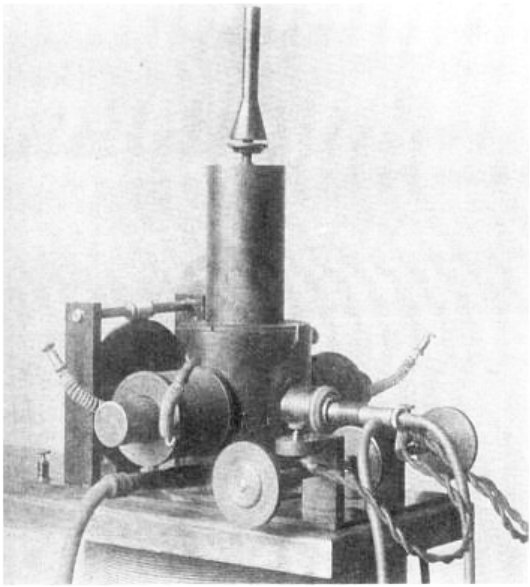
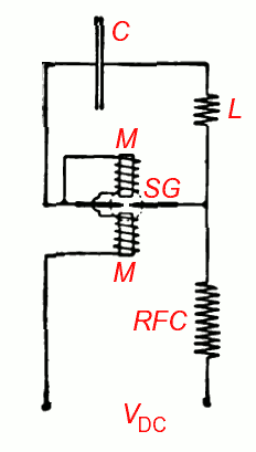
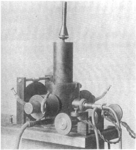
At its core, the Poulsen arc converter housed a chamber where an electric arc burned in hydrogen gas between a carbon cathode and a water-cooled copper anode. A tuned circuit was connected across the arc to select the desired frequency. Above and below the chamber, two series field coils surrounded the poles of a magnetic circuit, with those poles projecting into the chamber on either side of the arc to generate a magnetic field that stabilized operation. The device was most effective in the frequency band from a few kilohertz to a few tens of kilohertz, and its antenna tuning had to be sufficiently selective to suppress the abundant harmonics the arc naturally produced. Among the three recognized types of arc oscillators, the Poulsen arc occupied the second category: the condenser's alternating-current discharge was large enough to extinguish the arc each cycle but not large enough to reignite it in the opposite direction, yielding the clean continuous wave that distinguished it from both the Duddell arc and the quenched spark gap.
Keying, Interference, and the End of an Era
Because the arc required time to strike and reach stable operation, simple on-off keying was impractical. Instead, operators employed a compensation-wave technique: the arc ran continuously while the key shifted its frequency by one to five percent, producing a mark at one frequency and a space at another. For units up to 70 kilowatts, the key typically shorted a few turns of the antenna coil; larger arcs used transformer coupling with the key shorting turns on the grounded secondary. This method consumed considerable spectrum bandwidth and generated rich harmonics on both frequencies. Around 1921, the Preliminary International Communications Conference banned the compensation-wave method over interference concerns, and uniwave ignition methods—where a striker rod and electromagnet started and stopped the arc—offered a cleaner alternative. Yet by the 1920s, vacuum-tube transmitters rendered the arc obsolete. The Bureau of Standards had noted in 1922 that the arc accounted for roughly 80 percent of all energy radiated for radio purposes, a testament to its dominance before retirement. It now stands on the IEEE Milestones list as a historic achievement in electrical engineering.
Gallery

More in Radio Electronics 1-24
Spotted an error? Know more?
Reader corrections go straight into our review queue. Suggest an edit · How this site is sourced