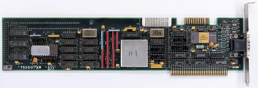
Television Interface Adaptor
Custom chip without framebuffer, driving the Atari 2600 display.

The Television Interface Adaptor (TIA) is a custom chip that, paired with a version of the MOS Technology 6502 processor, forms the core of the 1977 Atari Video Computer System. It handles screen output, sound, and controller input. Because RAM was very expensive when the console was designed, the TIA lacks a framebuffer; programmers had to write detailed code just to produce a basic display.
The TIA’s development was led by Jay Miner, who later expanded on its design for the Atari 8-bit computers with chips like ANTIC, CTIA/GTIA, and POKEY, which offered better graphics and sound. Miner eventually led the design of custom chips for the Amiga computer.
Around 1975, Atari engineers at Cyan Engineering, led by Steve Mayer and Ron Milner, were exploring alternatives to dedicated hardware for arcade and home games. Programmable microprocessors had appeared but were considered too costly for home use. At the time, most computer graphics used sprites drawn over a playfield, stored as bitmaps in a framebuffer—but RAM cost tens of thousands of dollars per megabyte. A simple two-color 80×48 display would have cost thousands in memory alone. NTSC televisions typically offered resolutions between 256 and 320 pixels per line and 192 to 240 lines per screen.
In September 1975, MOS Technology released the 6502, one of the first low-cost microprocessors. Mayer and Milner met with its designer, Chuck Peddle, to discuss using the 6502 for a programmable console. Over a few days, the basic design of the Atari VCS was sketched out. Peddle offered the lower-cost 6507 processor and the 6532 RAM-I/O-Timer (RIOT) chip. Using a breadboard prototype of the display adapter on a 6502 test system, Milner demonstrated a simple version of the game Tank. Joe Decuir was hired to turn the proof-of-concept into a working prototype, and Atari approved further development.
While Decuir worked on the rest of the system, Jay Miner focused on making an ASIC for the display adapter, which was named the Television Interface Adaptor. Because RAM remained expensive, the team abandoned the idea of a memory-based framebuffer.
Without a framebuffer, the TIA builds the screen by manipulating five movable graphic objects (two players, two missiles, and one ball) and a static playfield object. These are generated each scan line from their registers, requiring the program to update them line by line.
- Developer
- Jay Miner
- Part numbers
- CO10444/CO11903
- Graphics objects
- 5 movable objects (2 players, 2 missiles, 1 ball) plus a static playfield
- Horizontal resolution
- 160 visible color clock cycles per line
- Playfield width
- 20 bits (reflected or copied to 40 bits total)
- Color palette
- up to 128 colors
- Sound channels
- 2 channels of one-bit sound, 32 pitch values, 16 bit sequences, 4-bit volume control
Lore & Background
Around 1975, Atari engineers at Cyan Engineering, led by Steve Mayer and Ron Milner, considered alternatives to dedicated hardware for arcade and home video games. Programmable microprocessors were then too expensive for home use, and RAM cost tens of thousands of dollars per megabyte. In September 1975, MOS Technology introduced the 6502 microprocessor, and Mayer and Milner spoke with its designer Chuck Peddle. Over a couple of days, the basic design of the Atari VCS was laid out, with Peddle offering the lower-cost 6507 processor and the 6532 RAM-I/O-Timer (RIOT). Using a breadboard prototype, Milner demonstrated a simple version of Tank. Joe Decuir was hired to convert the proof-of-concept to a functional prototype, while Jay Miner focused on making an ASIC for the display adapter, named the Television Interface Adaptor (TIA). The cost of RAM remained high, so framebuffers were dropped from the TIA's design.
Reader's Guide
The TIA's significance lies in its RAM-less design, which forced programmers to compose the screen by manipulating five movable graphic objects (2 players, 2 missiles, 1 ball) and a static playfield object, all generated on every scan line from registers. This required the program to update registers on the fly, a process known as 'racing the beam.' The TIA provided hardware collision detection via 15 set/reset flip-flops, and used the CPU's RDY pin for synchronization. It also semi-automatically generated vertical sync signals, leaving the CPU to count lines and trigger sync. These constraints meant programmers had to time their code precisely; the part of a program handling this was called the 'kernel.' Early games tended to be simple and symmetric. The TIA's legacy includes its influence on later Atari chips: Miner continued at Atari expanding the TIA design for the Atari 8-bit computers with ANTIC, CTIA/GTIA, and POKEY, and later led the design of custom chips for the Amiga computer.
Did You Know?
- The TIA was designed without a framebuffer because RAM cost tens of thousands of dollars per megabyte at the time.
- The TIA uses a 'racing the beam' technique where the CPU must update registers for each scan line during the horizontal blanking period.
- The TIA provides hardware collision detection using 15 set/reset flip-flops, read typically during the VBLANK period.
- The TIA has no frame line-counter; the CPU must trigger vertical sync signals and count lines to end each frame.
More in Graphics Hardware, Part 2 1-24
Spotted an error? Know more?
Reader corrections go straight into our review queue. Suggest an edit · How this site is sourced