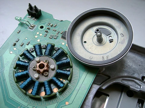
Synchronous motor
AC motor with shaft rotation locked to supply frequency.

MePaJa · CC BY-SA 4.0
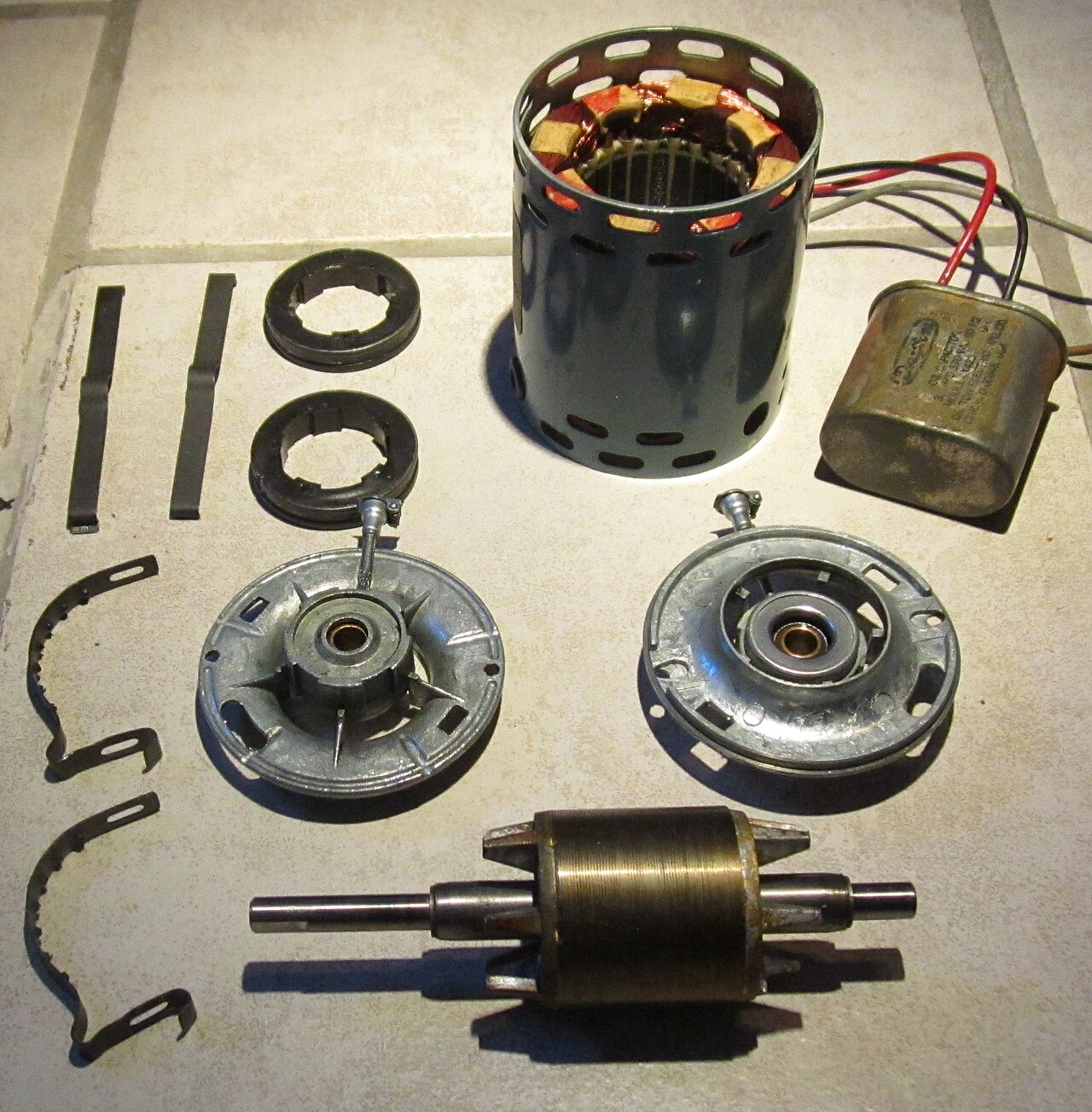
A synchronous motor is a type of AC motor where, under steady conditions, the shaft spins at a rate exactly matching the frequency of the incoming current. Its rotor can be built with either permanent magnets or electromagnets, while the stator always uses electromagnets. The stator produces a magnetic field that rotates in sync with the current's oscillations, and the rotor follows that field at the same speed, generating its own synchronized rotating magnetic field. Along with induction motors, synchronous motors are among the most common AC motor types. Unlike induction motors, which need slip (a slightly slower rotor speed to induce current), synchronous motors lock their rotation to the line frequency because they don't rely on induction for the rotor's magnetic field.
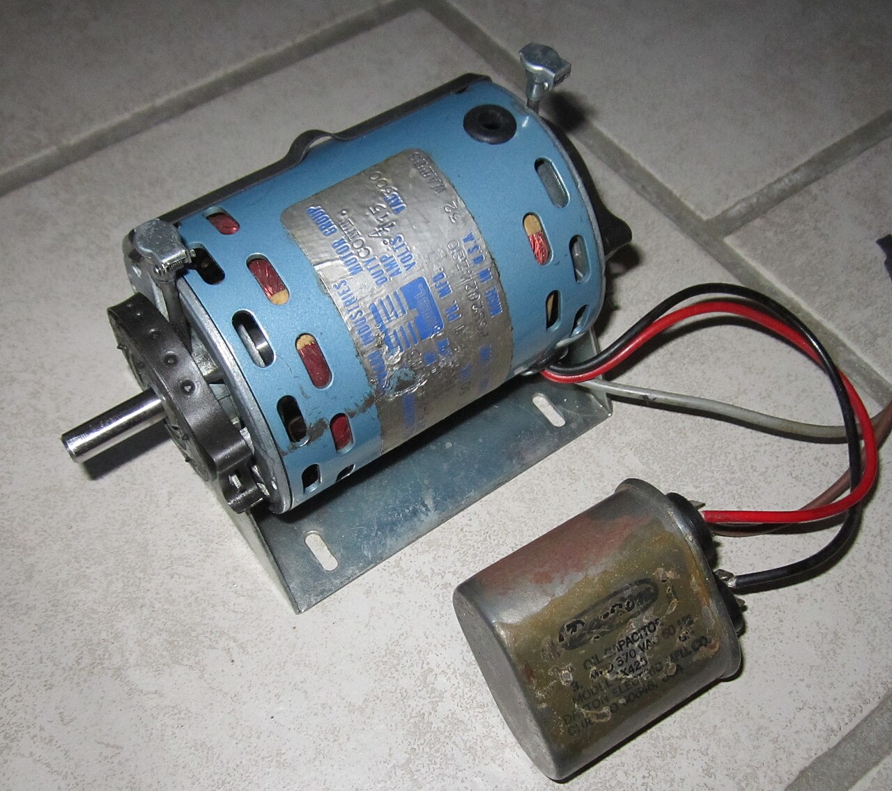
Small synchronous motors are often found in timing devices like analog clocks, appliance timers, tape recorders, and precision servomechanisms where exact speed is critical. Their accuracy depends on the power line frequency, which is tightly regulated in large grid systems. These motors come in self-excited versions and range from fractional horsepower to industrial sizes. In the fractional power range, they are mainly used for precise constant-speed applications. Doubly fed synchronous motors use independently powered multiphase AC electromagnets for both the rotor and stator.
In industrial sizes, synchronous motors efficiently convert AC energy into mechanical work, with electrical efficiency typically above 95% for larger units. They can operate at leading or unity power factor, helping to correct power factor in electrical systems. Synchronous motors are part of the broader category of synchronous machines, which also includes generators. Generator action happens when the field poles are pushed ahead of the air-gap flux by a prime mover, while motor action occurs when the field poles are pulled behind the air-gap flux by the load's retarding torque.
**Types**
The two main types of synchronous motors differ by how the rotor is magnetized: non-excited and direct-current excited.
**Non-excited**
In non-excited motors, the stator's external field magnetizes the rotor, creating the magnetic poles needed for rotation. The rotor turns in step with the stator's rotating field, maintaining an almost constant magnetic field.
- Efficiency
- above 95% is normal for larger sizes
- Power factor
- can operate at leading or unity power factor
- Synchronous speed formula
- Ns = 60 f / P (in RPM) or ωs = 2π f / P (in rad·s⁻¹)
- Typical industrial size
- larger than about 1 horsepower or 1 kilowatt for externally excited motors
- Reluctance motor power range
- from fractional horsepower (a few watts) to about 22 kW
Lore & Background
Synchronous motors are categorized into two major types by rotor magnetization: non-excited and direct-current excited. Non-excited motors include permanent-magnet, reluctance, and hysteresis designs. Permanent-magnet synchronous motors (PMSMs) use permanent magnets embedded in the rotor; neodymium magnets are most common, though ferrite magnets are also used, typically requiring spoke type rotors and resulting in lower power and torque density. Reluctance motors have a solid steel cast rotor with salient toothed poles, often with fewer rotor than stator poles, and typically include squirrel-cage windings for starting. Hysteresis motors have a solid cylindrical rotor of high-coercivity cobalt steel, developing constant torque from startup to synchronous speed and being self-starting.
Externally excited motors, usually made in larger sizes (above about 1 horsepower), require direct current to magnetize the rotor, supplied through slip rings or a brushless AC induction and rectifier arrangement. Control techniques for synchronous motors include scalar control, V/f control, vector control, field oriented control, direct torque control, and feedback linearization. PMSMs can also operate on open-loop control for start-up.
Reader's Guide
Synchronous motors are notable for their precise constant speed, which is locked to the line frequency, making them essential in timing applications such as synchronous clocks, timers in appliances, tape recorders, and precision servomechanisms. Their accuracy depends on the power line frequency, which is carefully controlled in large interconnected grid systems. In industrial sizes, synchronous motors provide efficient AC-to-work conversion with electrical efficiency above 95% for larger sizes, and they can operate at leading or unity power factor, thereby providing power-factor correction. The two major types—non-excited and direct-current excited—offer a range of designs for different applications, from fractional horsepower instrumentation to multi-horsepower industrial drives. PMSMs have been used as gearless elevator motors since 2000, and many require a variable-frequency drive to start, though line-start versions exist. Reluctance motors, when used with adjustable frequency power supplies, allow all motors in a drive system to operate at exactly the same speed. Hysteresis motors, though more expensive, are used where precise constant speed is required, primarily as servomotors and timing motors.
Did You Know?
- Synchronous motors rotate at a rate locked to the line frequency because they do not rely on induction to produce the rotor's magnetic field.
- Hysteresis motors develop constant torque from startup to synchronous speed because the lag angle δ is independent of speed.
- Reluctance motor designs have ratings that range from fractional horsepower (a few watts) to about 22 kW.
The Core Principle of Rotating Magnetic Fields
A brushless DC motor operates on a fundamental electromagnetic principle: torque is generated by maintaining a deliberate misalignment between the magnetic fields of the rotor and the stator. When direct current flows through the stator windings, it creates a magnetic field that the permanent magnet rotor naturally wants to align with. The key insight is that once alignment is reached, the field must be shifted to the next position, and the rotor follows, producing continuous rotation. An electronic controller manages this process by precisely adjusting the phase and amplitude of current pulses delivered to the windings. This timed switching effectively creates a magnetic field that rotates in space, and the rotor chases it around. Unlike brushed designs where current must be physically routed to a spinning component, the brushless architecture keeps all windings stationary on the stator while the rotor simply carries permanent magnets. This eliminates the need to connect current to a moving part, a design choice that underpins many of the motor's performance advantages.
From Mechanical Brushes to Solid-State Electronics
The transition from brushed to brushless commutation was made possible by the maturation of solid-state electronics in the 1960s. In a conventional brushed motor, a rotating cylinder segmented into metal contacts sits on the shaft, and stationary graphite brushes press against it to route current to whichever winding is in the correct angular position. This mechanical switching is inherently lossy and fragile. In the brushless approach, an electronic sensor continuously monitors the rotor's angular position and feeds that information to a controller. The controller then drives semiconductor switches—typically transistors—that reverse or cut off current in the stator windings at precisely the right moment. The result is the same timed phase distribution that a commutator provides, but achieved with no sliding contacts, no wear particles, and no sparking. The motor's operational lifespan is now governed solely by its bearings rather than by the gradual erosion of brush material. This shift from mechanical to electronic commutation represents one of the most consequential engineering upgrades in the history of electric motor design.
Why Brushed Motors Fell Short
Brushed DC motors, despite their century of industrial dominance, carry a constellation of drawbacks that ultimately confined them to low-power niches. The sliding contact between graphite brushes and commutator segments generates friction, which wastes energy as heat—particularly costly in small, low-power applications. The soft brush material steadily wears away, shedding particulate dust that contaminates sealed environments such as hard-disk-drive enclosures and that demands periodic brush replacement. The electrical resistance at the sliding interface produces a voltage drop known as brush drop, siphoning additional power from the circuit. Perhaps most critically, the abrupt current switching through inductive windings generates sparks at the contacts, posing a genuine fire risk in explosive atmospheres and radiating electromagnetic interference that disrupts nearby microelectronics. Over the past hundred years, high-power brushed DC machines were largely displaced by AC synchronous motors in industrial settings. Today, brushed designs survive mainly in low-power or DC-only contexts, but even there, their friction, wear, and noise limitations make them increasingly unattractive compared to their brushless counterparts.
Architectural Diversity and Everyday Applications
Brushless DC motors are not a single fixed design but a family of configurations that can be tailored to very different engineering needs. The stator and rotor geometry can follow an outrunner layout where the rotor encircles the stator, an inrunner layout with the stator wrapping the rotor, or an axial arrangement in which both are flat and parallel. The rotor magnets may be conventional permanent magnets or high-energy neodymium variants, and the underlying machine topology can resemble a permanent magnet synchronous motor, a switched reluctance motor, or even an induction motor. This flexibility has pushed brushless technology into an extraordinary range of applications: the spindle motors inside computer disk drives and printers, the compact power tools in a tradesperson's belt, the propulsion systems of model aircraft and full-size automobiles, and the direct-drive assemblies in modern washing machines—where a brushless motor has eliminated the rubber drive belt and gearbox entirely. The high power-to-weight ratio, near-instantaneous speed and torque control, and minimal maintenance requirements make the brushless motor a quietly ubiquitous presence in both consumer and industrial technology.
Gallery
More in Electric Motors, Part 3 1-24
Spotted an error? Know more?
Reader corrections go straight into our review queue. Suggest an edit · How this site is sourced