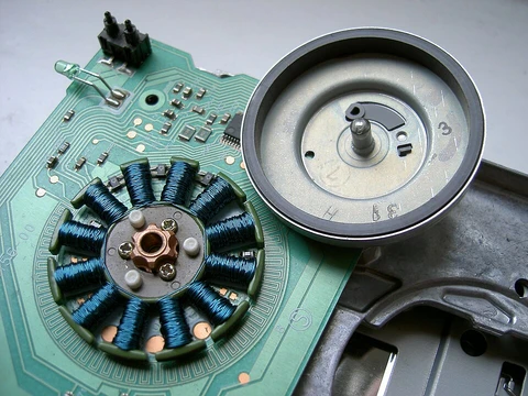
Synchronous condenser
A spinning motor that adjusts reactive power on the grid.

Mriya · CC BY-SA 3.0
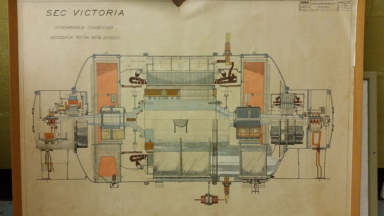
A synchronous condenser, also known as a syncon, synchronous capacitor, or synchronous compensator, is a DC-excited synchronous motor whose shaft spins freely without being connected to any mechanical load. Its purpose is not to convert electric power to mechanical power, but to adjust conditions on a three-phase electric power transmission grid by generating or absorbing reactive power as needed to regulate voltage or improve power factor.
- Typical rating range
- 20 MVAR to 200 MVAR
- Typical dimensions
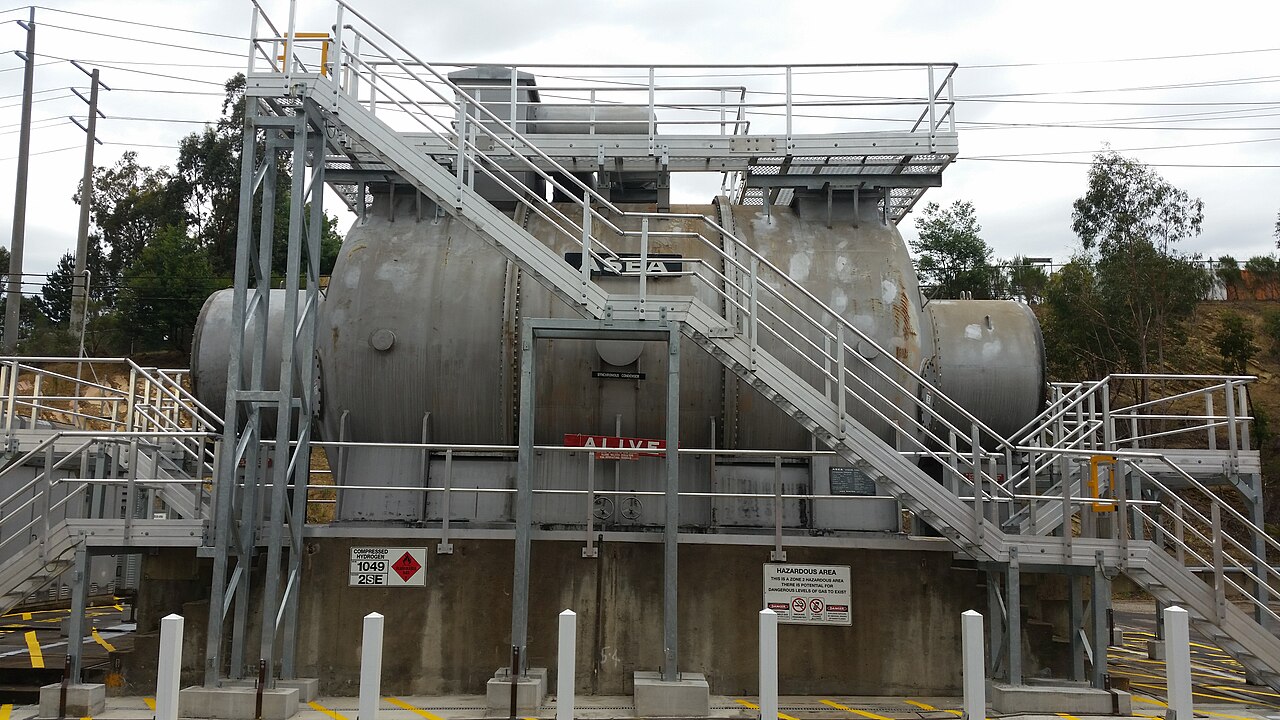
- 8 metres long, 5 metres tall
- Typical weight
- 170 tonnes
- Cooling method
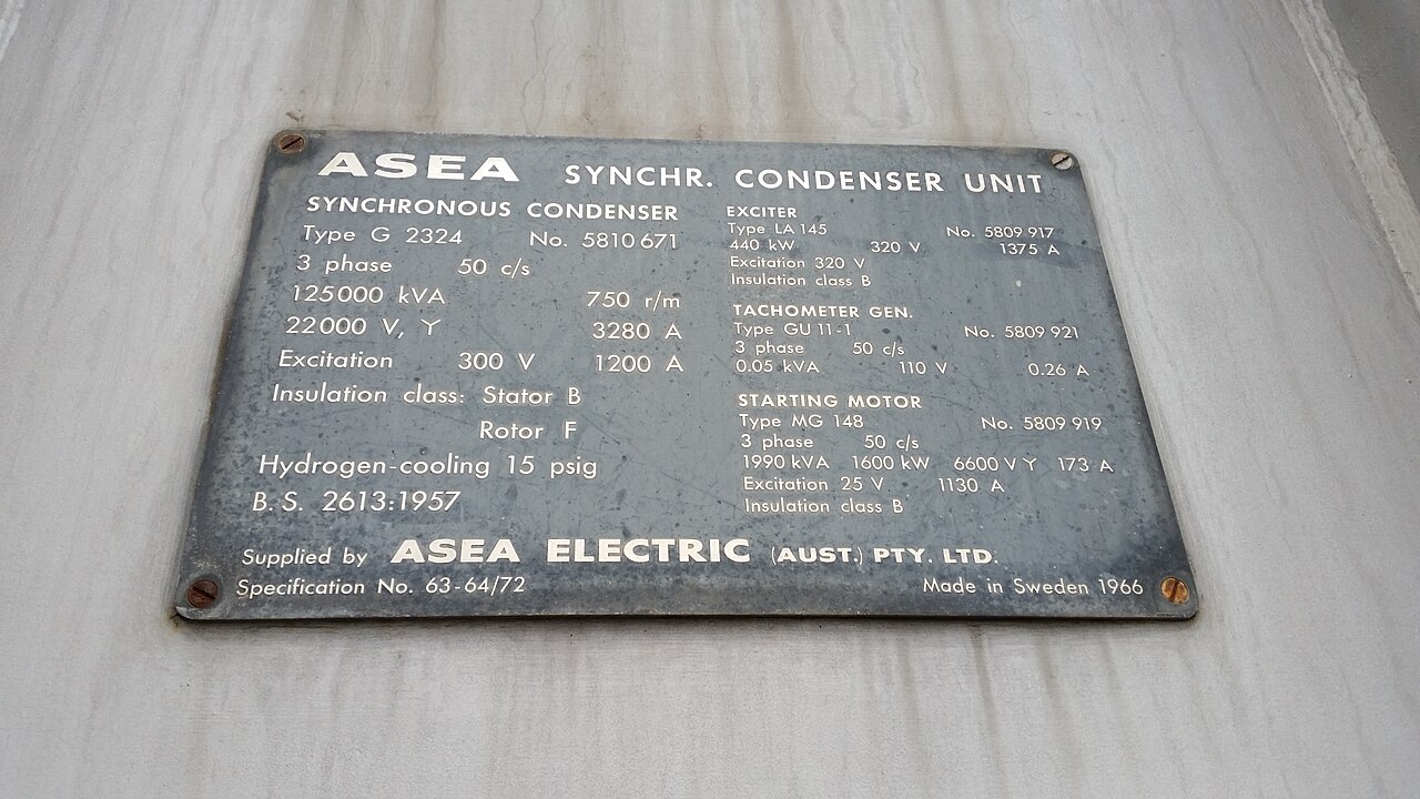
- hydrogen cooled
- Safe hydrogen concentration
- above 70%, typically above 91%
Lore & Background
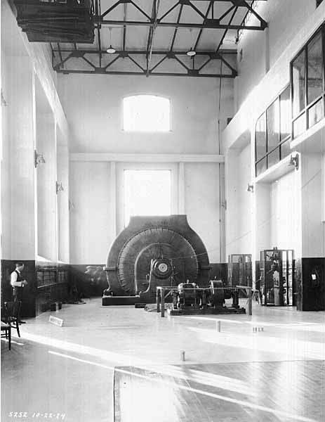
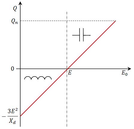
The synchronous condenser is a DC-excited synchronous motor with its shaft unconnected, operating identically to large electric motors and generators. Its field excitation is controlled by a voltage regulator to either generate or absorb reactive power. Increasing field excitation causes the device to furnish reactive power (measured in vars) to the system. The principal advantage is the ease with which the amount of correction can be adjusted.
Synchronous condensers are an alternative to capacitor banks and static VAR compensators for power-factor correction. One advantage is that reactive power from a synchronous condenser can be continuously adjusted, and it inherently increases when grid voltage decreases, unlike capacitor banks. They are also more tolerant of power fluctuations and severe voltage drops, though they have higher energy losses than static capacitor banks.
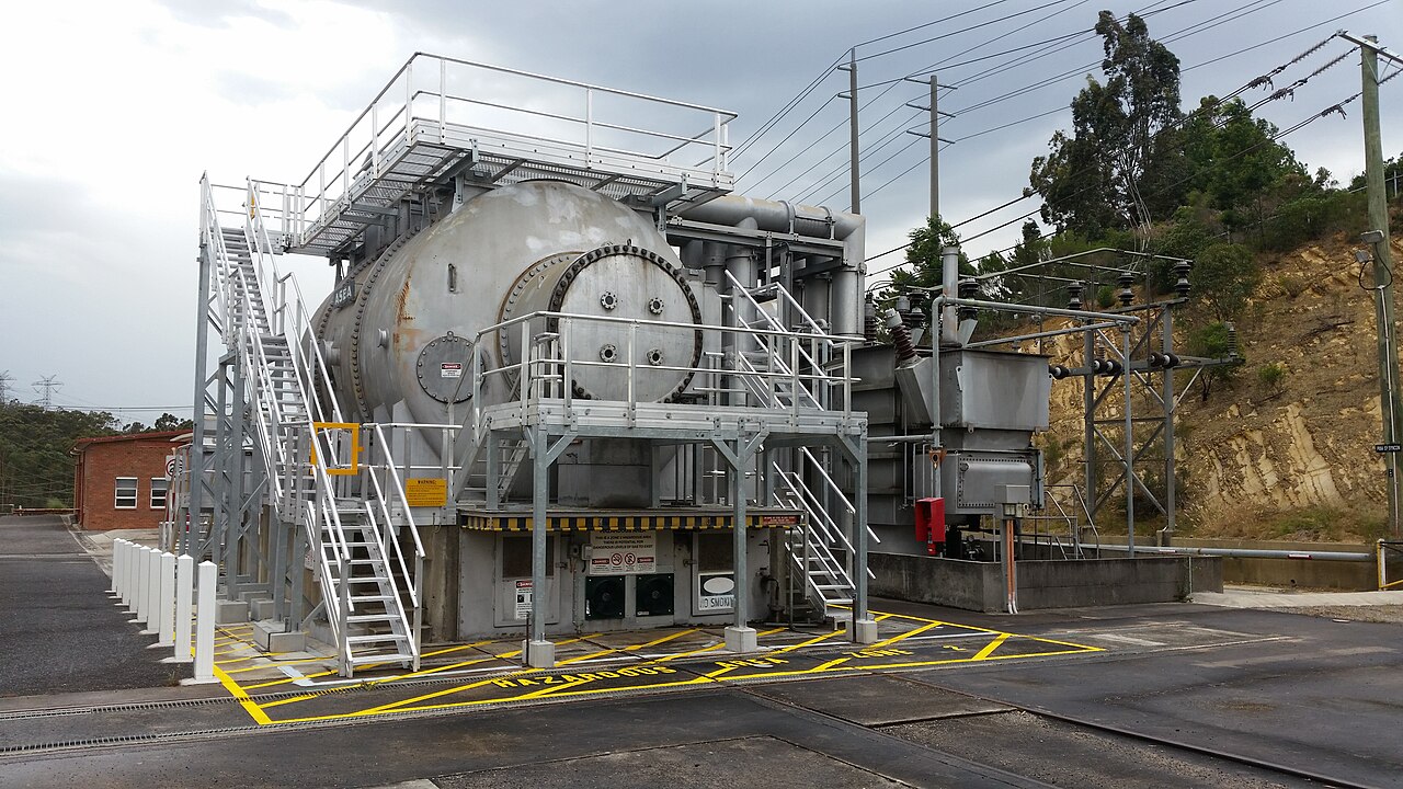
Most synchronous condensers connected to electrical grids are rated between 20 MVAR and 200 MVAR, and many are hydrogen cooled. There is no explosion hazard as long as the hydrogen concentration is maintained above 70%, typically above 91%. A syncon can be 8 metres long and 5 metres tall, weighing 170 tonnes.
Reader's Guide
Synchronous condensers help stabilize grids by providing inertial response during rapid load fluctuations, such as those from electric arc furnaces. Their inductance and high momentary power capabilities can help trigger breakers to clear faults created by short circuits. For these reasons, large installations of synchronous condensers are sometimes used alongside inverter-based technology. They are finding use in facilitating the switchover between power grids and alongside high-voltage direct current converter stations, providing power grid stabilization by reintroducing rotating inertia to compensate for the loss of rotational inertia from retiring rotating generator power plants as more inverter-based renewable energy plants come online. The theory behind their operation involves a rotating coil in a magnetic field producing a sine-wave voltage; when connected to a circuit, current flows depending on the difference between system voltage and open-circuit voltage. Mechanical torque corresponds only to real power, while reactive power does not result in any torque. The armature current varies with field excitation, producing V-shaped curves; when over-excited, the motor runs with leading power factor and supplies vars to the grid, and when under-excited, with lagging power factor and absorbs vars.
The Synchronous Advantage Over Induction
The defining distinction between a synchronous machine and its induction-motor counterpart lies in how torque is generated. An induction motor depends entirely on a small speed differential—called slip—between the stator's rotating field and the rotor shaft. That slip is what induces current in the rotor winding and, in turn, creates torque. Near synchronous speed, the induction mechanism effectively vanishes, so an induction motor simply cannot deliver rated torque at that point. A synchronous motor, by contrast, bypasses slip-induction altogether. It establishes its rotor field through one of three means: permanent magnets embedded in the rotor, salient poles with projecting magnetic geometry, or an independently excited winding fed with DC or AC current. Because the rotor field is self-sustaining rather than induced, the machine locks to the stator field and produces its full rated torque at precisely the synchronous speed. The brushless wound-rotor doubly fed variant extends this principle, allowing the rotor to operate at the supply frequency or at sub- or super-multiples of it, all without any commutator or slip-ring arrangement.
Anatomy of the Machine
Every AC motor, whether rotating or linear, is built around two cooperating elements. The outer stator carries coils that, when energized with alternating current, generate a continuously rotating magnetic field. Inside, the rotor is mounted on the output shaft and produces a second magnetic field of its own. Depending on the design, that rotor field may arise from permanent magnets, from the natural reluctance differences of a salient-pole geometry, or from electrical windings fed with either DC or AC current. In a conventional rotating configuration, these two fields interact to produce torque. In the less common linear variant, the same electromagnetic principles apply, but the stationary and moving components are laid out in a straight line, so the output is translational motion rather than rotation. The entire architecture—stator coils, rotor field source, and the air gap between them—works as a single electromagnetic system in which the stator field drags the rotor field along, and the rotor's own field provides the counter-reaction that converts electrical energy into mechanical work.
A Century of Convergence
The path to the modern synchronous machine stretched across more than half a century of parallel invention. The theoretical seed was sown in 1830–31 when Michael Faraday and Joseph Henry independently showed that a changing magnetic field could induce current in a circuit; Faraday, having published first, is usually credited. Two years later, French instrument maker Hippolyte Pixii built the first crude alternator—a revolving horseshoe magnet sweeping past two wound coils. The late nineteenth century saw a rush of inventors in Europe and the United States seeking practical AC motors, driven by AC's clear advantage in long-distance high-voltage transmission. Walter Baily demonstrated a commutator-assisted polyphase motor in London in 1879; Marcel Deprez published a two-phase rotating-field paper in 1880; Elihu Thomson expanded the induction-repulsion principle in 1886. Galileo Ferraris and Nikola Tesla independently produced commutatorless induction motors around 1885–1888, and Mikhail Dolivo-Dobrovolsky followed with the first three-phase induction motor in 1890, a design that became the industrial standard across Europe and America.
Speed, Frequency, and the Governing Equation
The rotational speed of any AC machine is governed by a deceptively simple relationship: synchronous speed equals 120 times the supply frequency divided by the number of poles per phase winding. The constant 120 is not arbitrary—it folds together the 60 seconds in a minute and the fact that each phase requires two poles. For an induction motor, the actual shaft speed always falls short of this theoretical value. The shortfall, called slip, arises because the rotor must lag the stator field just enough for current to be induced in its winding. Under no load the slip is tiny, limited only by internal mechanical losses; under normal loading, standard motors exhibit roughly two to three percent slip, while specialized designs may reach seven percent. A synchronous motor, however, is not subject to this constraint. Because its rotor field is established independently—through permanent magnets, salient-pole construction, or an externally excited winding—it locks to the stator field and turns at exactly the calculated synchronous speed, with no slip at all, regardless of the torque it is delivering.
Gallery
More in Electric Motors, Part 3 1-24
Spotted an error? Know more?
Reader corrections go straight into our review queue. Suggest an edit · How this site is sourced