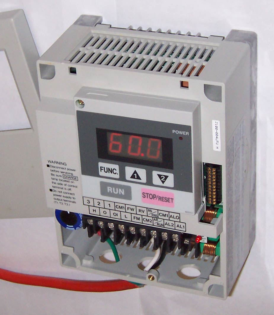
Sub-Micro AC Drive
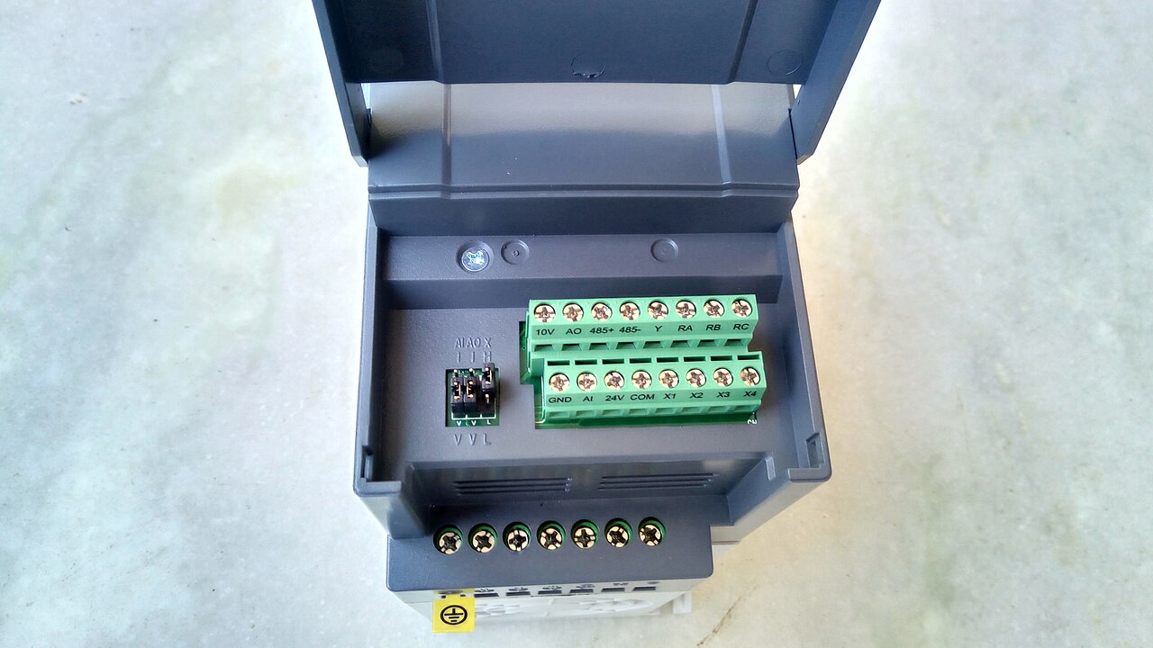
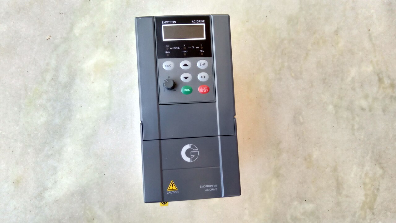
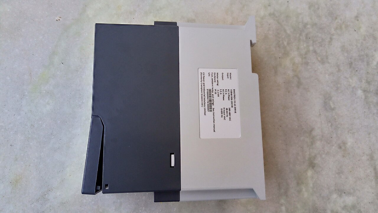
Compact VFD for small motor speed and torque control.

C J Cowie · CC BY-SA 3.0
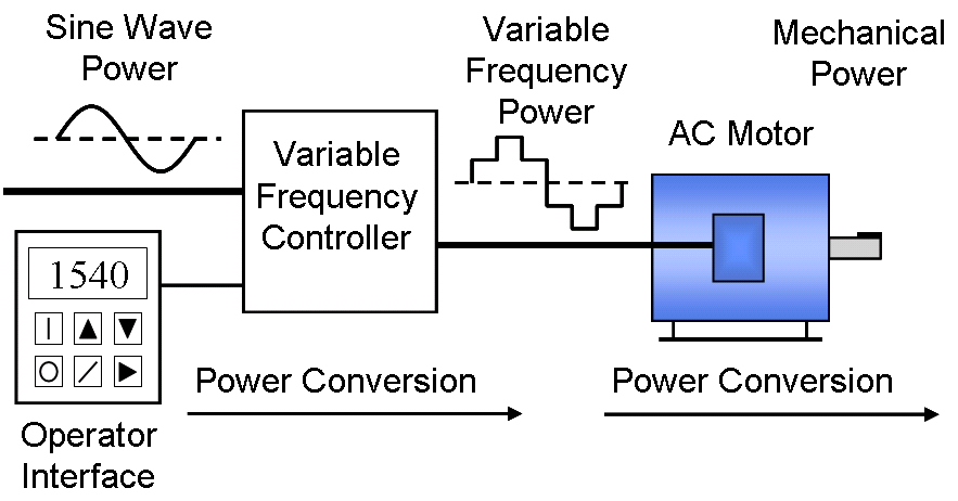
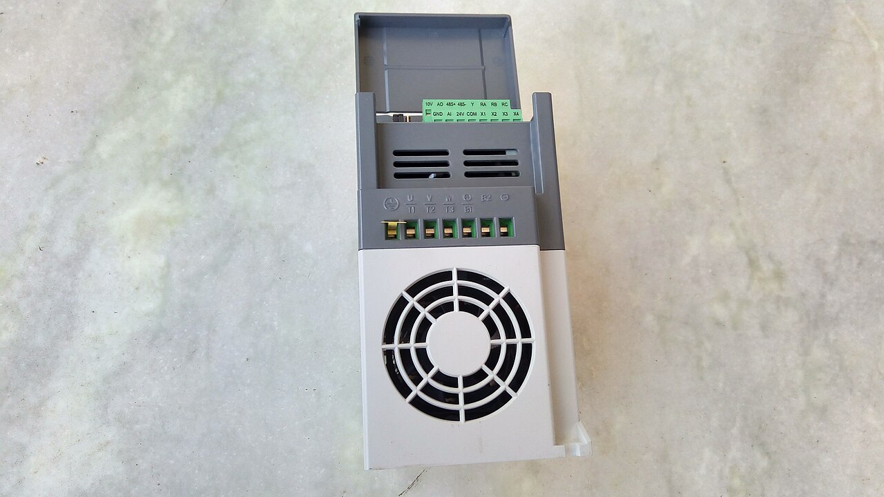
A sub-micro AC drive is a compact variable-frequency drive (VFD) used to control the speed and torque of an AC motor by varying the frequency of the input electricity. It is notable for its small size and low cost, enabled by advances in power electronics technology since the 1980s, including improvements in semiconductor switching devices and control techniques.
- Inventor
- Martti Harmoinen
- First pwm drive project start
- 1960s
- First operational pwm drive
- SAMI10, 1982
- Common motor type
- three-phase induction motor
- Dominant switching device
- insulated-gate bipolar transistor (IGBT), introduced in 1983
- Typical voltage frequency relationship
- 460 V, 60 Hz motors: 7.67 V/Hz
Lore & Background
The development of sub-micro AC drives traces back to pulse-width modulation (PWM) variable-frequency drive projects that started in the 1960s at Strömberg in Finland, where Martti Harmoinen is regarded as the inventor. The first PWM drive, SAMI10, became operational in 1982. Since the 1980s, power electronics technology has reduced VFD cost and size, allowing for sub-micro form factors. These drives typically use a voltage-source inverter (VSI) topology, which is the most common type, and employ a rectifier bridge converter, a DC link with a capacitor, and an inverter with active switching elements like IGBTs. Sub-micro AC drives are often used with three-phase induction motors, which are preferred as the most economical, though some single-phase or synchronous motors may be used in certain situations.
Reader's Guide
Sub-micro AC drives represent a significant legacy of the miniaturization and cost reduction in VFD technology driven by advances in power electronics since the 1980s. They are used in applications ranging from small appliances to larger systems, offering efficiency advantages over hydraulic systems in applications like pumps and fans. Their compact size allows integration into space-constrained equipment, while their control capabilities—such as Volts-per-Hertz (V/Hz) control, vector control, or direct torque control (DTC)—enable precise speed and torque regulation. The use of IGBTs, introduced in 1983, has become dominant in these drives. Sub-micro drives typically include an embedded microprocessor for overall control, with user programming via keypad, software, or SD card, and can be configured with optional components like EMC filters or braking resistors. Their legacy lies in making variable-speed control accessible for a wide range of low-power applications, contributing to energy savings and improved process control.
Did You Know?
- Martti Harmoinen is regarded as the inventor of PWM variable-frequency drive technology.
- The insulated-gate bipolar transistor (IGBT), introduced in 1983, has come to dominate VFDs as an inverter switching device.
Fundamental Architecture & Design
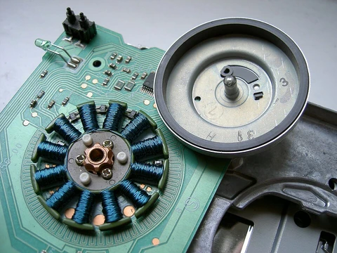
At its core, an AC motor is an electric machine that converts alternating current into mechanical motion. The conventional design pairs two fundamental assemblies: an outer stator wound with coils that, when fed alternating current, produce a continuously rotating magnetic field, and an inner rotor mounted on the output shaft that generates its own rotating field in response. Depending on the design, the rotor's magnetic field may be supplied by permanent magnets, by the geometry of reluctance saliency, or by electrical windings energized with either direct or alternating current. While most AC motors are built around a circular, rotating architecture, a less prevalent category known as the AC linear motor applies the same electromagnetic principles in a fundamentally different geometry. In that configuration, the stationary and moving components are laid out along a straight line, so the motor produces linear translational motion rather than the familiar rotational output.
The Two Great Families of Operation
The AC motor family splits into two dominant lineages: induction motors, also called asynchronous motors, and synchronous motors. The induction motor's entire operating logic rests on a small speed gap—termed slip—between the stator's rotating field and the actual rotor shaft speed. This relative motion is what induces current in the rotor's AC winding and thereby produces torque. A critical consequence is that an induction motor cannot deliver torque at or near synchronous speed, because the induction mechanism simply ceases to function when the relative motion vanishes. Synchronous motors take a fundamentally different approach: they do not depend on slip-induced current at all. Instead, they generate their rated torque at exactly synchronous speed using permanent magnets, salient projecting poles, or an independently excited rotor winding. One advanced variant, the brushless wound-rotor doubly fed synchronous motor, features an independently excited rotor and can operate at the supply frequency or at sub or super multiples of it. Beyond these two main families, eddy current motors and mechanically commutated AC and DC machines also exist, with speed governed by applied voltage and winding connection.
Historical Genesis & the Pioneers
The electromagnetic foundations of AC motor technology were laid in the 1830s, when Michael Faraday and Joseph Henry independently discovered that a changing magnetic field can induce an electric current in a nearby circuit; Faraday is generally credited because he published his findings first. Two years later, in 1832, French instrument maker Hippolyte Pixii constructed the first alternator—a revolving horseshoe magnet passing over two wound-wire coils that generated a crude form of alternating current. The practical development of AC motors accelerated in the late nineteenth century, fueled by the recognized advantage of alternating current in long-distance, high-voltage transmission. Walter Baily gave a working demonstration of a battery-operated polyphase motor with a commutator to the Physical Society of London in 1879, and Marcel Deprez published the rotating magnetic field principle in 1880. Galileo Ferraris and Nikola Tesla independently developed commutatorless induction motors in the mid-1880s, with Tesla patenting his design in 1888. Mikhail Dolivo-Dobrovolsky then introduced the first three-phase induction motor in 1890, a far more capable design that became the prototype for both European and American industrial use.
Speed, Slip & Performance Characteristics
The speed at which an AC motor operates is determined primarily by two variables: the frequency of the AC supply and the number of poles in the stator winding. The relationship is captured by the formula Ns = 120F/p, where Ns represents synchronous speed in revolutions per minute, F is the supply frequency in hertz, and p is the number of poles per phase. The constant 120 arises from combining 60 seconds per minute with the fact that each phase requires two poles. In a squirrel-cage induction motor, the rotor can never actually reach this synchronous speed. If it did, the magnetic flux at any fixed point on the rotor would remain unchanging, no current would be induced in the cage bars, and torque would drop to zero. The rotor therefore always lags slightly behind the field—a condition called slip. Loading the motor increases slip as the shaft slows, and even under no-load conditions, internal mechanical losses keep slip from reaching zero. Standard motors typically exhibit two to three percent slip under load, while specialized designs may allow up to seven percent.
Gallery
More in Electric Motors, Part 3 1-24
Spotted an error? Know more?
Reader corrections go straight into our review queue. Suggest an edit · How this site is sourced