Stepper motor
A brushless DC motor that rotates in discrete angular steps.

Kushagra Keshari · CC BY-SA 4.0
A stepper motor, sometimes called a step or stepping motor, is a brushless DC electric motor that moves in small, distinct angular steps. It can hold a specific step position without needing a feedback sensor, and its step position can be increased or decreased quickly to produce continuous rotation, or it can actively hold its position at a single step. These motors come in various sizes, speeds, step resolutions, and torque levels. Switched reluctance motors are essentially very large stepping motors with fewer poles, typically using closed-loop commutators.
**Mechanism**
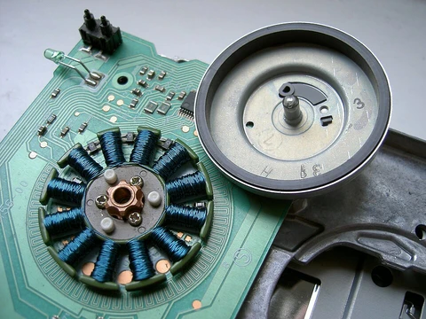
Unlike brushed DC motors, which spin continuously when voltage is applied, a stepper motor converts a series of input pulses—usually square waves—into a precise rotation of the shaft. Each pulse rotates the shaft by a fixed angle. The motor has multiple toothed electromagnets arranged as a stator around a gear-shaped iron rotor. An external driver circuit or microcontroller energizes these electromagnets. To turn the shaft, one electromagnet is powered, magnetically attracting the rotor’s teeth. When the teeth align with that electromagnet, they are slightly offset from the next one. Turning off the first electromagnet and powering the next causes the rotor to rotate slightly to align with the new one. This process repeats, with each partial rotation called a "step," and an integer number of steps makes a full rotation, allowing precise angular control.
The electromagnets are divided into groups called phases, each with an equal number of electromagnets. The designer chooses the number of phases, and the electromagnets of different phases are interleaved in a uniform pattern. For instance, a motor with two phases (A and B) and ten total electromagnets would have the pattern ABABABABAB. All electromagnets in the same phase are energized together, so motors with more phases generally have more wires or leads for control.
**Types**
There are three main types: permanent magnet, variable reluctance, and hybrid synchronous.
Permanent magnet (PM) motors have a permanent magnet rotor and operate by attraction or repulsion between the rotor magnet and stator electromagnets. Pulses move the rotor clockwise or counterclockwise in discrete steps.
- Types
- permanent magnet, variable reluctance, hybrid synchronous
- Common phases
- two phase, higher-phase count
- Winding arrangements for two phase
- bipolar and unipolar
- Typical leads for unipolar two phase mot
- six leads (or five if commons joined)
- Typical leads for bipolar two phase moto
- four leads (two per phase, none common)
- Efficiency of unipolar motor
- 50% (or approximately 70% of torque output available)
Lore & Background
Stepper motors effectively have multiple toothed electromagnets arranged as a stator around a central gear-shaped iron rotor. The electromagnets are energized by an external driver circuit or microcontroller. To make the shaft turn, one electromagnet is powered, attracting the gear's teeth; when aligned, the next electromagnet is turned on and the first off, causing the gear to rotate slightly. Each partial rotation is called a step, with an integer number of steps making a full rotation. The circular arrangement of electromagnets is divided into groups called phases, with an equal number of electromagnets per group, interleaved uniformly.
There are three main types: permanent magnet, variable reluctance, and hybrid synchronous. Permanent magnet motors use a permanent magnet rotor and have a detent when powered off. Variable reluctance motors have a soft iron rotor and detent only when powered on. Hybrid synchronous motors combine both types. Two-phase motors have two basic winding arrangements: unipolar (with center tap per phase, simpler drive) and bipolar (with single winding per phase, requiring H-bridge drive). Higher-phase count motors tend to have lower vibration and higher power density.
Reader's Guide
Stepper motors are significant for applications requiring precise angular positioning without feedback sensors, such as paper printers, 3D printers, and robotics, where position is tracked by counting steps. Their performance strongly depends on the driver circuit; torque curves can be extended to greater speeds by increasing drive voltage to overcome winding inductance and back-EMF. L/R driver circuits (constant voltage drives) are one approach. Unipolar motors are popular with hobbyists due to ease of operation with simple switching transistors, while bipolar motors are more powerful for the same weight because windings are better utilized, though they require more complex H-bridge drivers. The article notes that static friction effects have been observed with certain H-bridge drive topologies, and dithering the stepper signal at a higher frequency than the motor can respond to can reduce this effect. Multi-phase stepper motors, though more expensive, offer higher power density and are often better suited to applications with appropriate drive electronics.
Did You Know?
- Stepper motors can be set to any given step position without needing a position sensor for feedback.
- Permanent magnet stepper motors have a detent that remains at the shaft location even when current is removed.
- A unipolar stepper motor has twice the amount of wire in the same space as a bipolar motor, but only half is used at any point in time, making it 50% efficient.
- An 8-lead stepper motor can be wired in unipolar, bipolar with series windings, bipolar with parallel windings, or bipolar with a single winding per phase.
The Pulse-to-Position Principle
A stepper motor is fundamentally a device that translates electrical pulses into exact mechanical increments. Unlike a brushed DC motor that spins freely once voltage is applied, a stepper motor advances its shaft by a fixed angular amount for every input pulse it receives, typically a square wave. The stator consists of multiple toothed electromagnets arranged in a circle around a central gear-shaped iron rotor. When one electromagnet is energized, it magnetically pulls the nearest rotor teeth into alignment. Because those teeth are slightly offset from the adjacent electromagnet, switching to the next magnet causes a small additional rotation. Repeating this sequence produces continuous motion, while stopping at any point locks the shaft in place. No position sensor is required; the controller simply counts steps. The electromagnets are organized into groups called phases, interleaved in a uniform pattern—for instance, a ten-magnet, two-phase motor follows an ABABABABAB sequence. All coils within a single phase are energized simultaneously, meaning more phases demand more control wires.
Three Architectural Families
Stepper motors fall into three principal families, each exploiting a different magnetic interaction. Permanent magnet steppers place a magnet in the rotor; the stator coils attract or repel it to produce discrete steps. A key advantage is the detent torque: even with power removed, the magnet still resists movement, giving a predictable spring-like holding force with a defined torque limit before slippage occurs. This makes PM steppers well suited to paper printers, 3D printers, and robotics, where position is tracked simply by counting commanded steps. Variable reluctance steppers use a soft-iron rotor and rely on the principle that magnetic flux prefers the path of least air gap, pulling rotor points toward stator poles. They exhibit detent only while energized. Hybrid synchronous steppers merge both approaches, combining a permanent magnet with a variable-reluctance structure to extract maximum torque from a compact package. Switched reluctance motors, essentially very large stepping motors with fewer poles, represent an extension of the VR principle and typically employ closed-loop commutators.
Unipolar versus Bipolar Winding
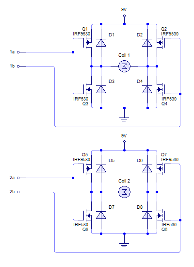
The way coils are wired inside a two-phase stepper motor dramatically affects both the driving electronics and the user experience. In a unipolar design, each phase contains a single winding with a center tap. Because the common wire never changes polarity, reversing a magnetic pole only requires switching which half of the winding is active, a job a single transistor per half-winding can handle. This simplicity, plus the fact that the two phase commons are often internally joined to yield just five leads, makes unipolar steppers the go-to choice for hobbyists seeking the cheapest route to precise angular control. Identifying the windings is straightforward: shorting a coil's two ends in a PM motor makes the shaft noticeably harder to turn, and the center tap can be spotted because its resistance to either end is exactly half the end-to-end resistance. Bipolar motors, by contrast, use a plain pair of leads per phase with no common. Reversing polarity demands an H-bridge or equivalent current-reversal circuit, making the driver more complex, though off-the-shelf driver chips have largely eliminated that burden. A typical excitation sequence for a two-coil bipolar unit cycles A+ then B+ then A− then B−.
Position Holding and Practical Versatility
One of the stepper motor's most distinctive traits is its ability to hold a precise angular position indefinitely without any feedback sensor. The controller issues a command to stop at a particular step, and the energized stator magnets simply lock the rotor teeth in place. If the step frequency is ramped up, the motor transitions smoothly into continuous rotation; ramp it down and it decelerates to a stop at an exact angle. This open-loop precision eliminates the cost and complexity of encoders in many applications. Motors come in a wide range of sizes, step resolutions, and torque ratings, letting designers match the device to tasks from fine printer carriage movement to heavy-duty robotic joints. The detent characteristics differ by type: PM motors retain a weaker holding force even after power is cut, while VR motors lose their detent entirely when de-energized. Multi-phase designs add more wires but finer granularity per revolution. Together, these attributes make the stepper motor a workhorse of motion control wherever repeatable, sensor-free positioning is the priority.
Gallery
More in Electric Motors, Part 3 1-24
Spotted an error? Know more?
Reader corrections go straight into our review queue. Suggest an edit · How this site is sourced