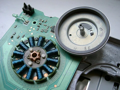
Rotor (electric)
Rotating component that produces torque via electromagnetic interaction.

The rotor is the rotating part inside an electric motor, generator, or alternator. It spins because the windings and magnetic fields interact, creating a twisting force (torque) around its central axis.
Early work on electromagnetic rotation began with Ányos Jedlik, who built the first rotary machine using electromagnets and a commutator in 1826–27. Other early contributors include Hippolyte Pixii, who made an alternating current generator in 1832, and William Ritchie, who built an electromagnetic generator with four rotor coils, a commutator, and brushes that same year. Practical applications soon followed: in 1834, Moritz Hermann Jacobi created a motor that could lift 10 to 12 pounds at one foot per second (about 15 watts of mechanical power). In 1835, Francis Watkins described an electrical "toy" he had built, and he is often credited as one of the first to realize that a motor and generator could be used interchangeably.
Rotors come in two main designs for induction (asynchronous) motors: squirrel-cage and wound. For generators and alternators (synchronous machines), the designs are salient pole or cylindrical.
A squirrel-cage rotor has a laminated steel core with evenly spaced bars of copper or aluminum running axially around its circumference. These bars are permanently connected at both ends by end rings. This simple, rugged construction makes it popular for most uses. The bars are slightly skewed (slanted) to reduce magnetic hum, slot harmonics, and the tendency of the rotor and stator teeth to lock together when they have the same number of teeth. Bearings at each end mount the rotor inside the housing; one shaft end sticks out to attach the load, and the non-driving end may have an extension for speed sensors or electronic controls. The torque generated moves the rotor, which drives the load.
A wound rotor has a cylindrical core made of steel laminations with slots that hold three-phase windings. These windings are spaced 120 electrical degrees apart and connected in a Y configuration. The rotor winding terminals are brought out to three slip rings on the shaft, with brushes making contact. External three-phase resistors can be connected in series to the rotor windings through these brushes and slip rings, allowing speed control. These external resistances become part of the rotor circuit, producing high torque when starting the motor.
- Early example
- First rotary machine built by Ányos Jedlik with electromagnets and a commutator, in 1826-27
- Early generator
- Hippolyte Pixii built an alternating current generator in 1832
- Early motor power
- Moritz Hermann Jacobi's motor could lift 10 to 12 pounds with a speed of one foot per second, about 15 watts of mechanical power in 1834
- Salient pole speed
- Operates at a speed below 1500 rpm
- Cylindrical rotor speed
- Operates at speed between 1500-3600 rpm
Lore & Background
An early example of electromagnetic rotation was the first rotary machine built by Ányos Jedlik with electromagnets and a commutator, in 1826-27. Other pioneers include Hippolyte Pixii, who built an alternating current generator in 1832, and William Ritchie's construction of an electromagnetic generator with four rotor coils, a commutator and brushes, also in 1832. Development quickly included more useful applications such as Moritz Hermann Jacobi's motor that could lift 10 to 12 pounds with a speed of one foot per second, about 15 watts of mechanical power in 1834. In 1835, Francis Watkins describes an electrical 'toy' he created; he is generally regarded as one of the first to understand the interchangeability of motor and generator.
There are two designs for the rotor in an induction motor: squirrel cage and wound. In generators and alternators, the rotor designs are salient pole or cylindrical. The squirrel-cage rotor consists of laminated steel in the core with evenly spaced bars of copper or aluminium placed axially around the periphery, permanently shorted at the ends by the end rings. The wound rotor is a cylindrical core made of steel lamination with slots to hold the wires for its 3-phase windings which are evenly spaced at 120 electrical degrees apart and connected in a 'Y' configuration.
A salient pole rotor is built upon a stack of 'star shaped' steel laminations, typically with 2 or 3 or 4 or 6, maybe even 18 or more 'radial prongs' sticking out from the middle, each of which is wound with copper wire to form a discrete outward facing electromagnet pole. The cylindrical shaped rotor is made of a solid steel shaft with slots running along the outside length of the cylinder for holding the field windings of the rotor which are laminated copper bars inserted into the slots and is secured by wedges.
Reader's Guide
The rotor is central to the operation of electric motors, generators, and alternators, as its rotation is driven by the torque produced from the interaction between windings and magnetic fields. The article describes several rotor types, each suited to different applications. The squirrel-cage rotor, with its simple and rugged construction of laminated steel and shorted bars, is favored for most applications due to its durability. The wound rotor allows for speed control via external resistors connected through slip rings and brushes, providing high starting torque. Salient pole rotors, with their large diameter and short axial length, operate at speeds below 1500 rpm and have low mechanical strength, while cylindrical rotors operate at higher speeds (1500-3600 rpm) with strong mechanical strength and a uniform air gap. The article notes that rotors are typically impregnated in varnish for electrical insulation, or encapsulated in epoxy for improved cooling and insulation in wet conditions. The operating principle for a three-phase induction machine involves alternating current creating a rotating magnetic flux that induces voltage in the rotor bars, generating torque. For alternators, direct current drives the field current in the rotor's wire coil, creating a magnetic field with north and south poles, and the direction of motor rotation can be manipulated by the rotor's design.
Did You Know?
- The squirrel-cage rotor bars are slanted, or skewed, to reduce magnetic hum and slot harmonics and to reduce the tendency of locking.
- A salient pole rotor typically has 2, 3, 4, 6, or even 18 or more radial prongs.
More in Electric Motors, Part 2 1-24
Spotted an error? Know more?
Reader corrections go straight into our review queue. Suggest an edit · How this site is sourced