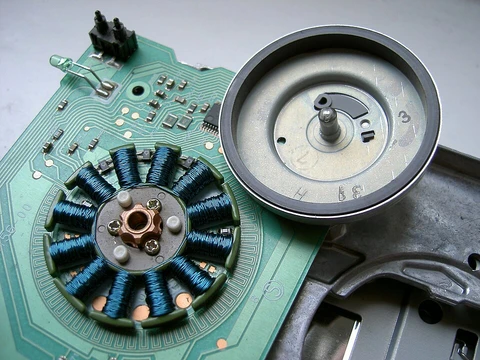
Magnet wire
Insulated copper or aluminium wire for coils in electromagnetic devices.

Magnet wire, often called enameled wire, is a thin, insulated copper or aluminum conductor. Its primary use is in devices that require tightly wound coils, such as transformers, inductors, motors, generators, speakers, headphones, hard disk head actuators, electromagnets, and electric guitar pickups. The conductor is usually fully annealed, electrolytically refined copper. Despite the name, the insulation is not a vitreous enamel or paint but a tough polymer film.
For construction, unalloyed pure metals, especially copper, are the most suitable materials. Copper is the first choice when considering chemical, physical, and mechanical properties. Fully annealed, electrolytically refined copper allows for closer winding in electromagnetic coils. For high-temperature applications in reducing atmospheres or hydrogen-cooled motors and generators, high-purity oxygen-free copper grades are used. Aluminum wire serves as an economical alternative for large transformers and motors, though it requires a cross-sectional area 1.6 times larger than copper to achieve the same DC resistance due to its lower conductivity.
Modern magnet wire insulation typically consists of one to four layers of polymer film, sometimes with two different compositions, to create a tough, continuous coating. Common insulating films, listed by increasing temperature tolerance, include polyvinyl formal (Formvar), polyurethane, polyamide, polyester, polyester-polyimide, polyamide-polyimide, and polyimide. Polyimide insulation can operate up to 250 °C (482 °F). Thicker square or rectangular wire often has its insulation augmented with high-temperature polyimide or fiberglass tape, and completed windings are frequently vacuum-impregnated with varnish for improved strength and reliability. Self-supporting coils use wire with at least two layers, where the outermost thermoplastic bonds turns together when heated. Other insulations like fiberglass yarn, aramid paper, kraft paper, mica, and polyester film are also common. In audio applications, silver wire is sometimes used, and insulators such as cotton (sometimes treated with beeswax) and polytetrafluoroethylene (Teflon) can be found. Older materials like cotton, paper, or silk are limited to low-temperature uses up to 105°C.
- Common temperature classes
- 105 °C, 130 °C, 155 °C, 180 °C, 220 °C
- Polyimide max operating temperature
- 250 °C (482 °F)
- Aluminium cross section ratio to copper
- 1.6 times larger for comparable DC resistance
- Current density range
- 2.5 A/mm² (isolated from free air) to 6 A/mm² (in free air)
- Insulation grades
- Grade 1, Grade 2, Grade 3 (higher grade = thicker insulation)
Lore & Background
Despite being called 'enameled,' modern magnet wire is not coated with vitreous enamel or enamel paint. Instead, it uses one to four layers of polymer film insulation, often of two different compositions, to provide a tough, continuous insulating layer. Insulating films include (in order of increasing temperature range) polyvinyl formal (Formvar), polyurethane, polyamide, polyester, polyester-polyimide, polyamide-polyimide, and polyimide, with polyimide capable of operation up to 250 °C. Thicker square or rectangular wire may be wrapped with high-temperature polyimide or fiberglass tape, and completed windings are often vacuum impregnated with insulating varnish. Self-supporting coils use wire with at least two layers, the outermost being a thermoplastic that bonds turns when heated. Older insulation materials such as cotton, paper, or silk are only useful for low-temperature applications up to 105 °C.
Reader's Guide
Magnet wire is fundamental to the construction of electric motors, transformers, inductors, generators, and many other electromagnetic devices. In electric motors, copper is commonly used in coil windings due to its high electrical conductivity, which reduces energy loss from coil resistance and enhances energy efficiency. For example, to reduce load losses in continuous-use induction-type motors above 1 horsepower, manufacturers invariably use copper. A high efficiency motor will usually have 20% more copper in the stator winding than its standard counterpart. Aluminium is an alternative in smaller horsepower motors, especially when not used continuously, and for large transformers and motors mainly for economical reasons. In transformers, copper is the predominant winding material in most areas of the world, though aluminium is a suitable competitor where weight and first cost are decisive. The choice of conductor material directly affects energy efficiency, with copper's greater conductivity contributing to improved energy efficiency in equipment such as electric motors.
Did You Know?
- Aluminium magnet wire requires 1.6 times the cross-sectional area of copper wire to achieve comparable DC resistance.
- Polyimide insulated magnet wire can operate at up to 250 °C (482 °F).
- Some low-temperature-grade magnet wire has insulation that can be removed by the heat of soldering.
- Thicker magnet wire often has a square, rectangular, or hexagonal cross-section for better packing and structural stability.
The Core Principle of Torque Generation
An electric motor generates rotational force by exploiting a fundamental magnetic principle: two fields must be kept deliberately out of alignment. In any motor design, the rotor and stator each carry a magnetic field—produced either by permanent magnets or by coils of wire wrapped around iron cores carrying direct current. The torque that drives the shaft arises precisely because these fields are misaligned, creating a force that attempts to realign them. Once the rotor begins turning and the fields start to align, the system must continuously shift one set of fields relative to the other to sustain that misalignment and keep torque flowing in a single direction. The component responsible for this timed switching is the commutator. In a brushless DC motor, this switching is handled electronically rather than mechanically, but the underlying physics remains the same: maintain the angular offset between rotor and stator fields, and the motor keeps spinning. The controller modulates both the phase and amplitude of current pulses delivered to the windings, giving precise command over rotational speed and torque output.
The Brush Commutator and Its Inherent Flaws
In conventional brushed DC motors, the commutation task is handled by a mechanical rotary switch mounted on the shaft. A cylinder or disc split into multiple metal segments rotates with the rotor, and two or more stationary graphite brushes press against these segments, sliding across them as the shaft turns. This sliding contact selectively feeds current into different windings, keeping the rotor's field misaligned with the stator's. Yet this elegant mechanical solution carries a long list of drawbacks. The friction between brush and commutator dissipates energy, a loss that becomes proportionally severe in small, low-power motors. The soft brush material gradually wears away, shedding particulate dust and eventually requiring replacement—making brushed designs unsuitable for sealed environments like hard-disk drives. The electrical resistance at the sliding interface produces a voltage drop that wastes additional power. Most critically, the abrupt current reversals through inductive windings generate sparks at the contacts, posing fire risks in explosive atmospheres and radiating electromagnetic interference that disrupts nearby microelectronics. Over the past century, these limitations have steadily pushed high-power applications toward AC synchronous machines, confining brushed motors to niche low-power roles.
The Electronic Revolution of the 1960s
The brushless DC motor became a practical reality only after solid-state electronics matured in the 1960s, providing the semiconductor switches needed to replace the mechanical commutator entirely. In a brushless design, an electronic sensor continuously tracks the angular position of the rotor. This position signal drives a bank of transistors that switch current through the stator windings at precisely the right moment—either reversing the current direction or cutting it off—so that the resulting magnetic field always pulls the permanent-magnet rotor forward in one consistent direction. Because no sliding electrical contacts exist, the motor suffers far less friction and its operational lifespan is governed solely by bearing wear rather than brush erosion. The rotor carries no windings, freeing it from centrifugal stress and allowing the stator windings to be thermally coupled to the housing for conduction cooling without internal airflow. The trade-off is that the control electronics are more complex, less rugged, and more expensive than a simple commutator, but the gains in efficiency, reliability, and reduced electromagnetic interference have made brushless architectures the preferred choice across a widening range of applications.
Where Brushless Motors Dominate Today
Brushless DC motors have become the default actuator in a remarkable breadth of modern devices. In computer peripherals, their sealed, spark-free operation makes them ideal for hard-disk drives and printers, where particulate contamination and electromagnetic noise are intolerable. Hand-held power tools benefit from the high power-to-weight ratio and near-instantaneous speed and torque control that electronic commutation provides. In the transportation sector, brushless motors power everything from small model aircraft to full-size automobiles. Perhaps the most visible domestic application is the modern washing machine, where a brushless DC motor has eliminated the need for rubber drive belts and multi-stage gearboxes, enabling a compact direct-drive architecture that transfers torque straight to the drum. The construction of these motors can vary widely—some use neodymium permanent magnets, and the rotor and stator may be arranged as outrunners, inrunners, or flat axial configurations—yet the shared advantages of high efficiency, low maintenance, quiet operation, and long service life remain constant regardless of geometry.
Frequently Asked Questions
What is Magnet wire?
Magnet wire is a thin copper or aluminum conductor wrapped in a tough polymer-film insulation, purpose-built for winding dense coils in motors, transformers, speakers, and other electromagnetic devices. Despite the name, the coating is not a glass enamel or paint but a durable polymer layer.
What material is Magnet wire made from?
The conductor is typically fully annealed, electrolytically refined pure copper, chosen for its outstanding electrical conductivity. Aluminum can serve as a substitute, though it needs a cross-section roughly 1.6 times larger to match copper's DC resistance.
How hot can Magnet wire operate?
Standard insulation temperature classes span 105 °C, 130 °C, 155 °C, 180 °C, and 220 °C, while polyimide-coated variants push the ceiling to 250 °C (482 °F). The exact rating depends on the specific polymer film and insulation grade applied.
Why is Magnet wire essential in electric motor design?
Without its ultra-thin polymer insulation, adjacent turns in a coil would short against each other, making multi-layer windings—and the electromagnetic fields they produce—impossible. It also lets designers pack current densities from about 2.5 A/mm² in thermally isolated positions up to roughly 6 A/mm² in free air.
What do insulation Grades 1, 2, and 3 mean?
These grades correspond to increasing thickness of the polymer film on the conductor, so a higher grade provides a more robust dielectric barrier. A motor designer picks the grade based on the voltage differential between neighboring turns and the mechanical stresses the winding will face in service.
More in Electric Motors, Part 2 1-24
Spotted an error? Know more?
Reader corrections go straight into our review queue. Suggest an edit · How this site is sourced