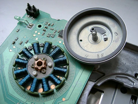
Low magnetic electric motor
Reduced magnetic stray field motor for naval mine countermeasures.

A low magnetic electric motor, also called a nonmagnetic electric motor, is a type of AC or DC motor designed to produce a weaker magnetic stray field than standard motors. These motors are installed on mine countermeasures vessels, minehunters, minesweepers, and certain submarines to help them avoid triggering naval mines that rely on magnetic fuzes.
Naval mines have been a part of sea warfare for about a century. Modern mines can react to magnetic, acoustic, or pressure signals, but the magnetic influence firing principle—which detects the magnetic interference field of a passing ship—was the most important advance. Magnetic-fuzed mines are effective, cheap, and simple to deploy. An electric motor generates two kinds of magnetic fields: a dynamic alternating stray field while running, and a static residual magnetic field when stopped. To avoid detection, these signatures must be reduced as much as possible at the source.
Electric motors create internal magnetic fields to spin the rotor inside the stator. A significant portion of these magnetic stray fields escapes the motor housing and can be detected. While running, motors also produce airborne and structure-borne noise. The main goal is to lower all these signatures for stealth operation. A ship’s overall signature is typically measured at a magnetic ranging facility.
Low magnetic motors are built with as little magnetic material as possible. Components are selected for low magnetic permeability. Three main methods reduce stray magnetic fields: a dedicated electric and magnetic design, electromagnetic shielding, and additional compensating coils. These reduction techniques are outlined in standards such as the American DOD-STD-2146, British Defence-Standard 02-717, and German BV3013. Further reduction of the motor’s magnetic signature, and the ship’s overall signature, can be achieved with degaussing coils.
The main source of airborne noise from an electric motor is its cooling fan. Reducing cooling air speed lowers this noise. Alternatively, water or oil cooling can be used. Airborne noise limits for naval equipment are set by standards like MIL-STD-1474D, British Defence Standard 02-813, or Indian Naval Engineering Standard NES 847.
- Standards mentioned
- DOD-STD-2146, Defence-Standard 02-717, BV3013, MIL-STD-1474D, Defence Standard 02-813, NES 847, MIL-STD-740-2(SH), MIL-STD-167-1A, NAVSEA-908-LP-000-3010, MIL-S-901D, BR3021, BV 0230, MIL-STD-810
- Users
- Osprey-class, Tripartite-class, Huon-class, Oksøy-class, Alta-class, Sandown-class, Lerici-class, Katanpää-class, Kormoran 2-class minehunters; Visby-class korvette
Lore & Background
Low magnetic electric motors are designed to reduce the emanating magnetic stray field signature, which is critical for avoiding detection by naval mines that use the magnetic influence firing principle. These motors are manufactured from as little magnetic material as possible, with components selected for low magnetic permeability. Three major means of reduction are a dedicated electric and magnetic layout, electromagnetic shielding, and additional compensating coils. Further reduction can be obtained by additional degaussing coils.
The motors also address airborne and structure borne noise, as well as vibration and shock. Airborne noise primarily comes from the cooling fan and can be reduced by lowering cooling air speed or using water or oil cooling. Structure borne noise results from roller bearing inaccuracies, rotor bar pass frequencies, magnetic unbalance, and non-matching rotor and stator slot combinations. Vibration from mechanical unbalance is reduced by precision balancing, and external shock and vibration are handled by rigid design and shock mounts.
Shock resistance is necessary due to underwater explosions, and testing is performed by specialist institutes such as TNO, NTS Navy, Thales-ECC, or QinitiQ. Standards from American, British, German, and Indian sources govern the reduction and measurement of these signatures.
Reader's Guide
The significance of low magnetic electric motors lies in their role in naval stealth and mine countermeasures. For about a hundred years, sea mines have been an established element in naval warfare, and the magnetic influence firing principle is the most important step in their development. By reducing the magnetic stray field at the source, these motors allow vessels to operate in stealth mode, avoiding detection by magnetic fuzes. The motors are used on a wide range of minehunters and minesweepers, including the Osprey, Tripartite, Huon, Oksøy, Alta, Sandown, Lerici, Katanpää, and Kormoran 2 classes, as well as the Visby-class korvette. The legacy of these motors is embedded in multiple military standards that define reduction methods and acceptance criteria, ensuring consistent performance across navies. Their design principles—minimizing magnetic material, using shielding and compensating coils, and addressing noise and vibration—have become standard for any equipment requiring a low magnetic signature.
Did You Know?
- Low magnetic electric motors are used on mine countermeasures vessels, minehunters, minesweepers, and specific types of submarines.
- The motors produce a dynamic alternating stray field while running and a static remnant magnetic field at standstill.
- Three major means of reducing magnetic stray fields are dedicated layout, electromagnetic shielding, and compensating coils.
- Airborne noise reduction can be achieved by using water or oil cooled electric motors instead of fan cooling.
Core Operating Principle
A brushless DC motor operates as a synchronous machine that draws its energy from a direct current supply. At its heart, the device relies on a simple yet elegant principle: the magnetic fields of the rotor and the stator are deliberately kept out of alignment, and the resulting torque drives the rotor to turn. In a brushless design, the rotor typically carries permanent magnets, while the stator holds the current-carrying windings. An electronic controller sits between the power source and the windings, rapidly switching the direction and magnitude of the current that flows through each coil. By adjusting both the phase and the amplitude of these current pulses, the controller shapes the rotating magnetic field in space, and the permanent-magnet rotor simply chases that field. Because the commutation is handled electronically rather than mechanically, the motor can deliver precise, nearly instantaneous adjustments to both rotational speed and torque, making it a highly responsive actuator for a wide range of tasks.
Replacing the Brush Commutator
The invention of solid-state electronics during the 1960s opened the door to a fundamentally different way of commutating a DC motor. In a traditional brushed motor, a rotating cylinder of segmented metal contacts on the shaft works together with stationary graphite brushes to route current into the correct winding as the rotor spins. That sliding-contact arrangement, however, generates friction losses, sheds abrasive dust, produces a measurable voltage drop, and throws off sparks that create electromagnetic interference and pose a fire risk in flammable environments. The brushless approach eliminates every one of those problems by replacing the mechanical switch with a small electronic sensor that reads the rotor's angular position and a bank of semiconductor transistors that switch current through the stator windings at precisely the right moment. With no brushes pressing against a commutator, the motor suffers far less mechanical wear, runs quieter, and its service life is governed almost entirely by the longevity of its bearings rather than by eroding contact material.
Construction and Design Flexibility
Although the brushless DC motor is most often built in a configuration closely resembling a permanent-magnet synchronous motor, the underlying architecture allows considerable variation. The stator windings may be paired with a switched-reluctance rotor or even an induction (asynchronous) rotor, broadening the family of machines that fall under the brushless umbrella. Where permanent magnets are used, high-strength neodymium magnets are a common choice. The spatial relationship between rotor and stator can take at least three distinct forms: an outrunner layout in which the rotor encircles the stator, an inrunner layout in which the stator surrounds the rotor, and an axial arrangement in which both elements lie flat and parallel to one another. Because the windings are fixed to the stationary housing rather than spinning on the rotor, they are not subjected to centrifugal forces and can be cooled by conduction through the frame, removing the need for internal airflow and simplifying thermal management.
Applications and Practical Benefits
The combination of a high power-to-weight ratio, near-instantaneous speed and torque control, high electrical efficiency, and minimal maintenance has made the brushless DC motor a workhorse across an impressively wide spectrum of applications. In the computing world, they quietly drive disk drives and printers; in the workshop, they power hand-held electric tools; and in transportation, they propel everything from small model aircraft to full-size automobiles. One particularly striking example is the modern washing machine, where a brushless DC motor has allowed engineers to discard the rubber drive belt and the multi-speed gearbox in favor of a direct-drive coupling between the motor and the drum, simplifying the mechanism and reducing wear points. The elimination of ionizing sparks and the reduction of electromagnetic interference also make these motors well suited to sealed, low-particulate, or electronically sensitive environments where a brushed motor's commutator would be a liability.
Frequently Asked Questions
What exactly is a low magnetic electric motor?
It is a specialized AC or DC motor engineered so that the stray magnetic field it leaks into the surrounding environment is significantly weaker than that of a conventional motor. The design goal is to keep the vessel's overall magnetic signature below the detection threshold of magnetic-fuze naval mines.
Why do minehunters and minesweepers specifically need these motors?
Magnetic-influence mines detonate when they sense the distorted field of a passing steel hull, so every onboard component that adds to that signature is a liability. By fitting low-magnetic motors, the ship reduces one of the largest controllable sources of stray flux, lowering the chance of a premature detonation while sweeping or hunting.
Which real-world fleets and ship classes are known to use low magnetic electric motors?
They appear on a wide range of mine countermeasures platforms, including the Osprey-, Tripartite-, Huon-, Oksøy-, Alta-, Sandown-, Lerici-, Katanpää-, and Kormoran 2-class minehunters, as well as the Visby-class korvette. Certain submarines also carry them because a submerged hull is even more vulnerable to a magnetic trigger at close range.
What military or naval standards define the magnetic-field limits these motors must meet?
Several specifications set the allowable stray-flux ceilings, including DOD-STD-2146, Defence Standard 02-717, BV3013, MIL-STD-1474D, Defence Standard 02-813, NES 847, MIL-STD-740-2(SH), MIL-STD-167-1A, NAVSEA-908-LP-000-3010, MIL-S-901D, BR3021, BV 0230, and MIL-STD-810. Together they cover everything from the motor's own field output to the broader shipboard electromagnetic environment.
How does a low magnetic motor actually achieve a weaker field compared to a standard motor?
Designers adjust the stator and rotor geometry, use non-magnetic or low-permeability structural materials, and carefully manage the winding layout so that the net flux seen from outside the housing is minimized. The result is a motor that still delivers the required torque for propulsion or auxiliary drives while keeping its external magnetic footprint well below the thresholds that a mine's fuze would register.
More in Electric Motors, Part 2 1-24
Spotted an error? Know more?
Reader corrections go straight into our review queue. Suggest an edit · How this site is sourced