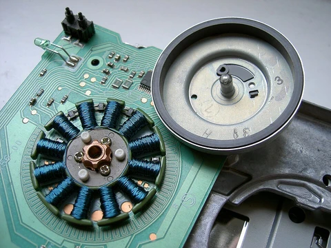
Lavet-type stepping motor
Single-phase stepping motor used in quartz clocks and wristwatches.

The Lavet-type stepping motor is a special kind of single-phase stepping motor widely used as a drive in electro-mechanical clocks. It is notable for its use in both analog and stepped-movement quartz clocks, and through miniaturization it can be used in wristwatches, requiring very little power to make a battery last for many years.
- Inventor
- Marius Lavet
- Patent application
- FR823395
- Patent filing date
- 28.09.1936
- Patent applicant
- Hatot
- Patent language
- french
- Additional patent
- US application 4550279
- Additional patent filing date
- 07.09.1983
Lore & Background
The Lavet-type stepping motor was invented by French engineer Marius Lavet and described in his 1936 patent application FR823395. Like other single-phase motors, it is only able to turn in one direction, which depends on the geometry of its stator. The rotor is a permanent magnet. In a clock, a circuit generates a bipolar pulse train, alternately delivering positive and negative voltage to the coil for short periods to provide correct mechanical output to move a second hand. The motor can be built with a strong magnet and large stator to deliver high torque, but is mostly built small to drive the load through a low gear ratio.
The stator core resembles that of a shaded-pole motor and defines rotational direction according to the position of holes, grooves, or shade windings. Unlike a shaded-pole motor, the grooves are at backward positions, and the positions where the rotor settles after each cycle are well determined. Essential for movement are the cogging points of the rotor, which differ depending on whether the stator coil is energized or unenergized. The cogging points with no current are caused by reluctant force against a direct magnetic field, and in practice are the angles where the air volume between the poles of the magnetic rotor and the bulk of the stator is minimized.
Movement of the common two-step Lavet motor proceeds as follows: (a) currentless stator, north pole of rotor points to the upper left; (b) energized stator, rotor moves clockwise, north pole points to the right; (c) after energization declines, rotor moves further until north pole points downright; (d) stator energized in opposite direction, rotor moves clockwise, north pole points to the left; (a') after energization declines, rotor moves to its initial position. To make the motor turn, the current through its stator coil must change direction each step (bipolar) followed by an interval without current while the rotor moves to its reluctant position.
Reader's Guide
The Lavet-type stepping motor is significant as the core drive mechanism in electro-mechanical clocks, enabling both analog and stepped-movement quartz timepieces to operate with minimal power consumption. Its invention by Marius Lavet in 1936, documented in patent FR823395, established a design that remains in widespread use. The motor's ability to be miniaturized for wristwatches, where it requires very little power and allows a battery to last many years, underscores its practical importance. The article notes that aside from clock drives, there are many variations of Lavet's concept, including types of dashboard instruments in cars. The motor's operation relies on a bipolar pulse train and well-defined cogging points, distinguishing it from induction motors where slip and load affect the rotor angle each cycle. The design's reliance on stator geometry to determine rotational direction and its use of a permanent magnet rotor are key characteristics. The article also references a later US patent (4550279) by Eric Klein, which explains the concept in English, indicating ongoing development and documentation of the technology. Overall, the Lavet motor's legacy is its efficient, reliable stepping action that has become standard in quartz timekeeping and other low-power applications.
Did You Know?
- The motor requires very little power, making a battery last for many years in wristwatches.
- The stator core looks like that of a shaded-pole motor, but the grooves are at backward positions.
- The motor's movement relies on cogging points that differ depending on whether the stator coil is energized or unenergized.
The Stepping Principle
A stepper motor transforms a sequence of electrical pulses into precisely quantified angular displacement of its shaft. At its core, the device pairs a gear-shaped iron rotor with multiple toothed electromagnets arranged in a circular stator. An external driver or microcontroller energizes these magnets one group at a time. When the first group is activated, the rotor's teeth are drawn into alignment with those poles. Because the next group of magnets sits at a slight angular offset, switching power to it and away from the first causes the rotor to nudge forward just enough to seat its teeth against the new poles. Repeating this cycle produces a train of tiny, fixed-angle rotations—each one called a step—so that an integer number of steps always yields exactly one full revolution. The circular magnet array is partitioned into equal groups known as phases, with members of different phases interleaved to form a uniform pattern around the stator. All magnets belonging to the same phase are energized simultaneously, which is why a higher phase count translates directly into more control leads on the motor housing.
Three Families of Stepper Design
Stepper motors fall into three principal design families, each exploiting a different magnetic interaction to achieve discrete rotation. Permanent magnet (PM) variants place a fixed magnet on the rotor, so movement is governed by the attraction and repulsion between that rotor magnet and the stator coils. A key advantage is the strong detent torque that persists even after current is removed, allowing the shaft to resist external spring or mechanical loads while still holding position. Variable reluctance (VR) designs instead use a soft-iron rotor and rely on the principle that magnetic flux prefers the path of least gap; the rotor points are drawn toward stator poles to minimize reluctance. Unlike PM types, VR motors lose their holding detent the instant power is cut. Hybrid synchronous motors merge both philosophies—combining a permanent magnet with a variable-reluctance toothed structure—to pack maximum torque into a compact form factor. Across all three types, the step position can be rapidly incremented or decremented for continuous rotation, or the motor can be commanded to lock firmly at a single angular location.
Winding Topologies and Phase Architecture
Two-phase stepper motors offer two fundamentally different winding layouts: unipolar and bipolar. In the unipolar arrangement, each phase carries a single winding with a center tap, producing three leads per phase (six total for a two-phase motor, often reduced to five when the two commons are internally joined). Because reversing a magnetic pole simply means energizing the opposite half of the winding rather than flipping current direction, the commutation circuit can be as simple as one switching transistor per half-winding. This simplicity makes unipolar motors a favorite among hobbyists and the most economical route to precise angular control. Bipolar motors, by contrast, use a pair of single-winding connections per phase with no common lead. Reversing polarity requires the current to flow in the opposite direction, so the drive circuit typically employs an H-bridge topology. A standard two-coil bipolar drive sequence alternates positive and negative current through coil A, then coil B, in the pattern A+ B+ A− B−. Off-the-shelf driver chips now make this otherwise more complex circuitry straightforward to implement.
Open-Loop Precision and Practical Applications
The defining practical advantage of a stepper motor is its ability to reach any commanded angular position without a feedback sensor. Because each input pulse produces a fixed, known increment of rotation, a controller simply counts the number of steps issued and knows exactly where the shaft must be. This open-loop architecture eliminates the cost and complexity of encoders or resolvers, making steppers exceptionally well suited to paper printers, 3D printers, and robotics, where position is tracked purely by step counting. Permanent magnet variants further benefit from a predictable spring-rate detent at the final step, with a specified torque limit beyond which slippage occurs; even with current removed, a lesser detent still resists external torque, and stepping can resume in perfect synchronization with the control electronics. Motors in this family vary widely in physical size, rotational speed, step resolution, and available torque, allowing designers to match the device to the task. Switched reluctance motors, which are essentially very large stepping motors with a reduced pole count, represent the industrial-scale extension of the same stepping principle, typically employing closed-loop commutators for their massive torque demands.
Frequently Asked Questions
Who is Lavet-type stepping motor?
It is a single-phase stepping motor designed by French engineer Marius Lavet, whose original design was filed under patent application FR823395 on 28 September 1936 with Hatot as the applicant. A later U.S. application (4550279) extended its protection to American markets.
What are Lavet-type stepping motor's powers and role?
Its core function is to advance the hands of electro-mechanical and stepped-movement quartz clocks one discrete step at a time using only a single phase of drive signal. Because it draws extremely little current per step, a small battery can keep a watch ticking for several years without replacement.
Why is Lavet-type stepping motor important to the fan community?
It is the hidden workhorse that made affordable, battery-powered quartz timekeeping possible in both tabletop clocks and wristwatches. Without its low-power single-phase stepping action, the multi-year battery life that defines modern quartz watches would be far harder to achieve.
What is Lavet-type stepping motor's origin and backstory?
Marius Lavet conceived the mechanism in France, and the design was formally lodged with the French patent office under applicant Hatot in the late 1930s. The French-language filing (FR823395) and the subsequent U.S. application 4550279 together mark the two key chapters of its early canon.
More in Electric Motors, Part 2 1-24
Spotted an error? Know more?
Reader corrections go straight into our review queue. Suggest an edit · How this site is sourced