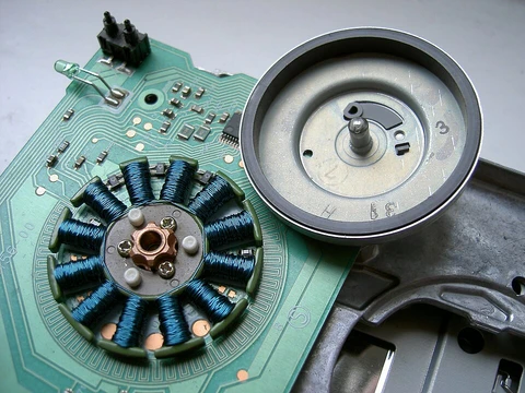
Motor constants
Motor constants describe torque, speed, and power loss characteristics.

Motor constants are values used to describe characteristics of electrical motors. The motor size constant (K_M) and motor velocity constant (K_v, also called the back EMF constant) are key parameters for motor selection and winding design.
- K m units
- N·m/√W
- K v units
- RPM per volt or rad/V·s
- K m definition
- τ/√P
- K v definition
- ω_no-load / V_peak
- K e units
- V·s/rad or V/krpm
Lore & Background
The motor constant K_M is expressed in newton metres per square root watt and is defined as torque divided by the square root of resistive power loss. It is winding independent as long as the same conductive material is used; for example, winding a motor with 6 turns with 2 parallel wires instead of 12 turns single wire doubles K_v but leaves K_M unchanged. K_M can be used for selecting the size of a motor, while K_v can be used for selecting the winding. Since torque is current multiplied by K_T, K_M also equals K_T divided by the square root of resistance. If two motors with the same K_v and torque work in tandem with rigidly connected shafts, the K_v of the system remains the same assuming a parallel electrical connection, while K_M increases by √2 because both torque and losses double. Alternatively, the system could run at the same torque with torque and current split equally, halving resistive losses.
Reader's Guide
The motor constant K_M is significant for sizing motors in applications, as it relates torque to resistive power loss and is independent of winding configuration. K_v is crucial for determining the unloaded rotational speed of a brushless motor relative to peak voltage; for instance, a motor with K_v = 5,700 rpm/V supplied with 11.1 V will run at a nominal speed of 63,270 rpm, though non-linear mechanical losses may prevent reaching this speed. When driven as a generator, the no-load voltage between terminals is perfectly proportional to RPM and true to K_v. The terms K_e and K_b are also used for the back EMF constant, often expressed in V·s/rad, which is an inverse measure of K_v. These constants enable engineers to match motors to specific torque, speed, and efficiency requirements.
Did You Know?
- K_v is measured in revolutions per minute per volt or radians per volt second.
- K_M remains unchanged when winding is altered with the same conductive material.
- If two identical motors are combined, the system's K_M increases by √2.
How a Brushless Motor Generates Motion
A brushless DC motor operates as a synchronous machine powered by a direct current supply, yet it produces the effect of a rotating magnetic field without any mechanical switching hardware. At its core, the motor relies on a permanent magnet rotor chasing a field that an electronic controller continuously steers through the stator windings. The controller reads the rotor's angular position via a sensor and then commands semiconductor switches—typically transistors—to route current through the appropriate windings at precisely the right moment. By adjusting both the phase and the amplitude of each current pulse, the controller governs the motor's rotational speed and the torque it delivers. The underlying physics is straightforward: torque arises whenever the rotor's magnetic field and the stator's field are held out of alignment. As the rotor turns and the fields begin to line up, the controller shifts the energized winding so the misalignment is restored, and rotation continues. This entirely electronic commutation replaces the sliding-contact commutator found in older brushed designs, eliminating the mechanical wear that once limited motor life to the lifespan of its brushes.
Why the Brush Commutator Became a Bottleneck
For much of the twentieth century, the standard way to keep a DC motor turning was a mechanical commutator: a segmented metal cylinder mounted on the rotor shaft, pressed against by soft graphite brushes that slid across its surface as it spun. This arrangement worked, but it carried a constellation of drawbacks that engineers increasingly found intolerable. The sliding contact generated friction that wasted a meaningful share of energy, especially in small, low-power motors. The graphite brushes eroded over time, shedding particulate dust and eventually requiring replacement—making them unsuitable for sealed or clean-room environments such as hard-disk drives. The electrical resistance at the brush interface produced a voltage drop that consumed additional power. Perhaps most critically, the abrupt switching of current through inductive windings sparked at the commutator contacts, creating a genuine fire risk in explosive atmospheres and generating electromagnetic interference that disrupted nearby microelectronics. Over the decades, high-power brushed DC machines were largely displaced by AC synchronous motors, and brushed designs retreated into low-power or DC-only niches where their limitations still constrained performance.
Construction Variations and Design Freedom
Although the term brushless DC motor most commonly evokes a permanent-magnet synchronous machine, the underlying architecture admits considerable variation. The stator-and-rotor relationship can be realized as a permanent magnet synchronous motor, a switched reluctance motor, or even an induction motor, each with its own electromagnetic character. Magnets of different compositions are possible, with neodymium-based magnets offering particularly strong fields. The physical layout is equally flexible: in an outrunner configuration the rotor encircles the stator, in an inrunner the stator encircles the rotor, and in an axial design the two sit flat and parallel to one another. A defining structural feature across most brushless designs is that the permanent magnets rotate around a fixed armature, so no electrical connections need to be made to the moving part. Because the windings are anchored to the stationary housing rather than spun on the rotor, they are immune to centrifugal stress and can shed heat by conduction through the frame, removing the need for internal airflow and simplifying sealing.
Where Brushless Motors Have Made Their Mark
The practical advantages of brushless commutation—high power-to-weight ratio, near-instantaneous speed and torque control, high efficiency, and minimal maintenance—have pushed the technology into an unusually wide range of products. In consumer electronics, they drive the spindle motors inside disk drives and the paper-feeding mechanisms of printers, where the elimination of brush dust and the absence of sparking make them ideal for sealed, precision environments. Hand-held power tools benefit from the high torque density and low noise that come with no mechanical commutation. In transportation, brushless motors power everything from small model aircraft to full-size automobiles. One of the most visible domestic applications is the modern washing machine, where a brushless DC motor has allowed manufacturers to discard the rubber drive belt and gearbox in favor of a direct-drive arrangement, reducing parts count and maintenance. The trade-off for these gains is a more complex and somewhat more expensive solid-state controller, but for most applications the reliability and efficiency dividends far outweigh that cost.
Frequently Asked Questions
What are Motor constants?
Motor constants are a pair of numerical descriptors—K_M (the size constant) and K_v (the velocity or back-EMF constant)—that together summarise how a particular motor converts electrical input into torque and rotational speed.
How is K_M defined and what are its units?
K_M is calculated as torque divided by the square root of the motor's power loss (τ/√P) and is expressed in newton-metres per square-root-watt (N·m/√W). It captures how efficiently a given motor geometry produces torque for a specified amount of dissipated power.
What does K_v actually measure?
K_v is the ratio of a motor's no-load angular speed to the peak voltage applied to its terminals, commonly quoted in RPM per volt or rad/(V·s). It lets an engineer predict the free-spin speed of a motor at a given supply voltage before any mechanical load is attached.
How do K_M and K_v work together in practice?
Because K_M encodes the torque-per-loss characteristic while K_v encodes the speed-per-voltage characteristic, a designer uses both side by side to match a motor's torque, speed, and thermal behaviour to a specific application. The two constants are complementary: a high-torque, low-speed winding will show a large K_M and a small K_v, and the reverse is true for a high-speed, low-torque winding.
Why are Motor constants important for motor selection and winding design?
They reduce the full electrical and mechanical behaviour of a motor to two comparable numbers, making it straightforward to rank candidate motors or to iterate on a winding layout. In practice, K_M and K_v are the first parameters an engineer checks when sizing a motor for a drone, an EV drive, or an industrial actuator.
More in Electric Motors, Part 2 1-24
Spotted an error? Know more?
Reader corrections go straight into our review queue. Suggest an edit · How this site is sourced