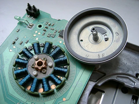
Reluctance motor
Reluctance motors induce magnetic poles on a ferromagnetic rotor without windings.

A reluctance motor is an electric motor that creates temporary magnetic poles on a rotor made of ferromagnetic material. The rotor contains no windings. The motor produces torque by exploiting magnetic reluctance—the tendency of magnetic flux to follow the path of least opposition. These motors offer high power density at a low cost, which makes them appealing for a variety of uses.
However, they have drawbacks, including significant torque ripple—the variation between the highest and lowest torque during a single revolution—especially at low speeds, along with noise caused by this ripple. Until the early 2000s, their adoption was hindered by the difficulty of designing and controlling them. Progress in theory, computer-aided design tools, and affordable embedded control systems resolved these issues. Microcontrollers use real-time control algorithms to adjust drive waveforms based on rotor position and feedback from current and voltage. Before the advent of large-scale integrated circuits, the necessary control electronics were prohibitively expensive.
**Design and Operating Fundamentals**
The stator features multiple projecting electromagnet poles, similar to those in a wound-field brushed DC motor. The rotor is made of soft magnetic material, like laminated silicon steel, with projections that act as salient magnetic poles via reluctance. In switched reluctance motors, the rotor typically has fewer poles than the stator, which reduces torque ripple and prevents all poles from aligning at once—a state where no torque can be generated.
When a rotor pole sits midway between two adjacent stator poles, it is in the "fully unaligned position," the point of highest magnetic reluctance for that pole. In the "aligned position," two or more rotor poles directly face two or more stator poles, creating a state of minimum reluctance. Energizing a stator pole produces torque that moves the rotor to reduce reluctance, pulling the nearest rotor pole from the unaligned position into alignment (the same principle used in a solenoid or when picking up ferromagnetic metal with a magnet). To keep rotating, the stator field must lead the rotor poles, constantly pulling them along.
- Peak efficiency
- 94%
- Power output experiment
- 23 kW at 14,000 RPM
- Power density experiment
- 1.4 kW
- Magnetization limit dual phase
- 1.5 T
- Conventional motor magnetization
- 2 T
- Comparable conventional rotor output
- 3.7 kW
Lore & Background
Until the early twenty-first century, the use of reluctance motors was limited by the complexity of designing and controlling them. Advances in theory, computer design tools, and low-cost embedded systems for control overcame these obstacles. Microcontrollers use real-time computing control algorithms to tailor drive waveforms according to rotor position and current/voltage feedback. Before the development of large-scale integrated circuits, the control electronics were prohibitively costly.
The stator consists of multiple projecting (salient) electromagnet poles, similar to a wound field brushed DC motor. The rotor consists of soft magnetic material, such as laminated silicon steel, which has multiple projections acting as salient magnetic poles through magnetic reluctance. When a stator pole is energized, the rotor torque is in the direction that reduces reluctance, pulling the nearest rotor pole into alignment. To sustain rotation, the stator field must rotate in advance of the rotor poles.
Reluctance motor subtypes include synchronous, variable, switched, and variable stepping. Disadvantages include high torque ripple when operated at low speed, and noise due to torque ripple. For switched reluctance motors, the number of rotor poles is typically less than the number of stator poles, which minimizes torque ripple and prevents the poles from all aligning simultaneously.
Reader's Guide
The reluctance motor is notable for its simple rotor construction—no windings or permanent magnets—and its ability to deliver high power density at low cost. Its use was historically constrained by control complexity, but advances in theory, computer design tools, and low-cost embedded systems overcame these obstacles. Microcontrollers now enable real-time control algorithms that tailor drive waveforms based on rotor position and feedback. The motor's subtypes, particularly the switched reluctance type, have become dominant due to electronic commutation providing advantages for starting, speed control, and smooth operation. Applications include analog electric meters, hard disk drive motors, electric vehicles, and power tools. A 2023 study demonstrated a dual-phase magnetic laminate rotor that achieved 23 kW at 14,000 RPM with 94% peak efficiency, though magnetization is limited to 1.5 T compared to 2 T in conventional motors. The motor's legacy lies in its cost-effective high power density and the overcoming of control challenges through modern electronics.
Did You Know?
- The rotor of a reluctance motor has no windings and induces non-permanent magnetic poles.
- Torque ripple in reluctance motors is the difference between maximum and minimum torque during one revolution.
- A 2023 experiment using a dual-phase rotor achieved 23 kW at 14,000 RPM with 94% peak efficiency.
More in Electric Motors, Part 2 1-24
Spotted an error? Know more?
Reader corrections go straight into our review queue. Suggest an edit · How this site is sourced