
Keyboard matrix circuit
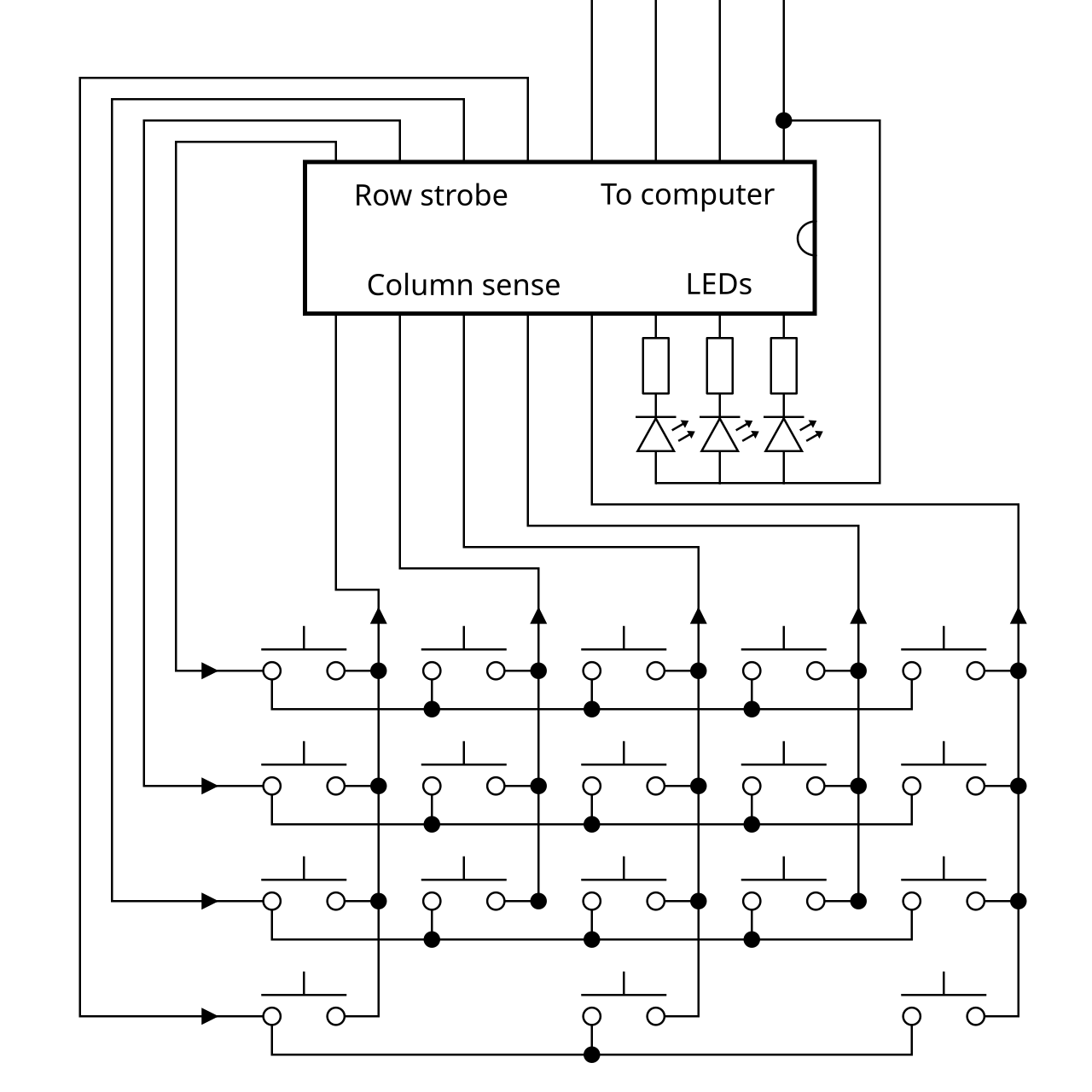
A grid of wires connecting key switches for efficient scanning.

Daniel beardsmore · Public domain
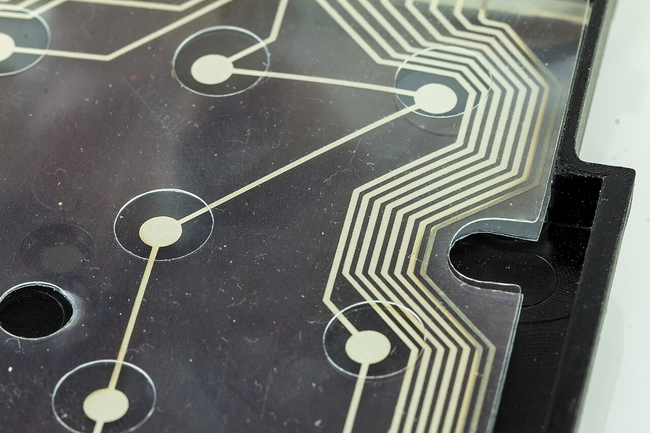
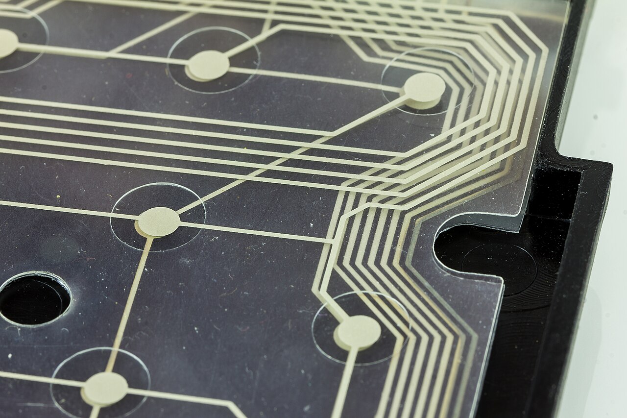
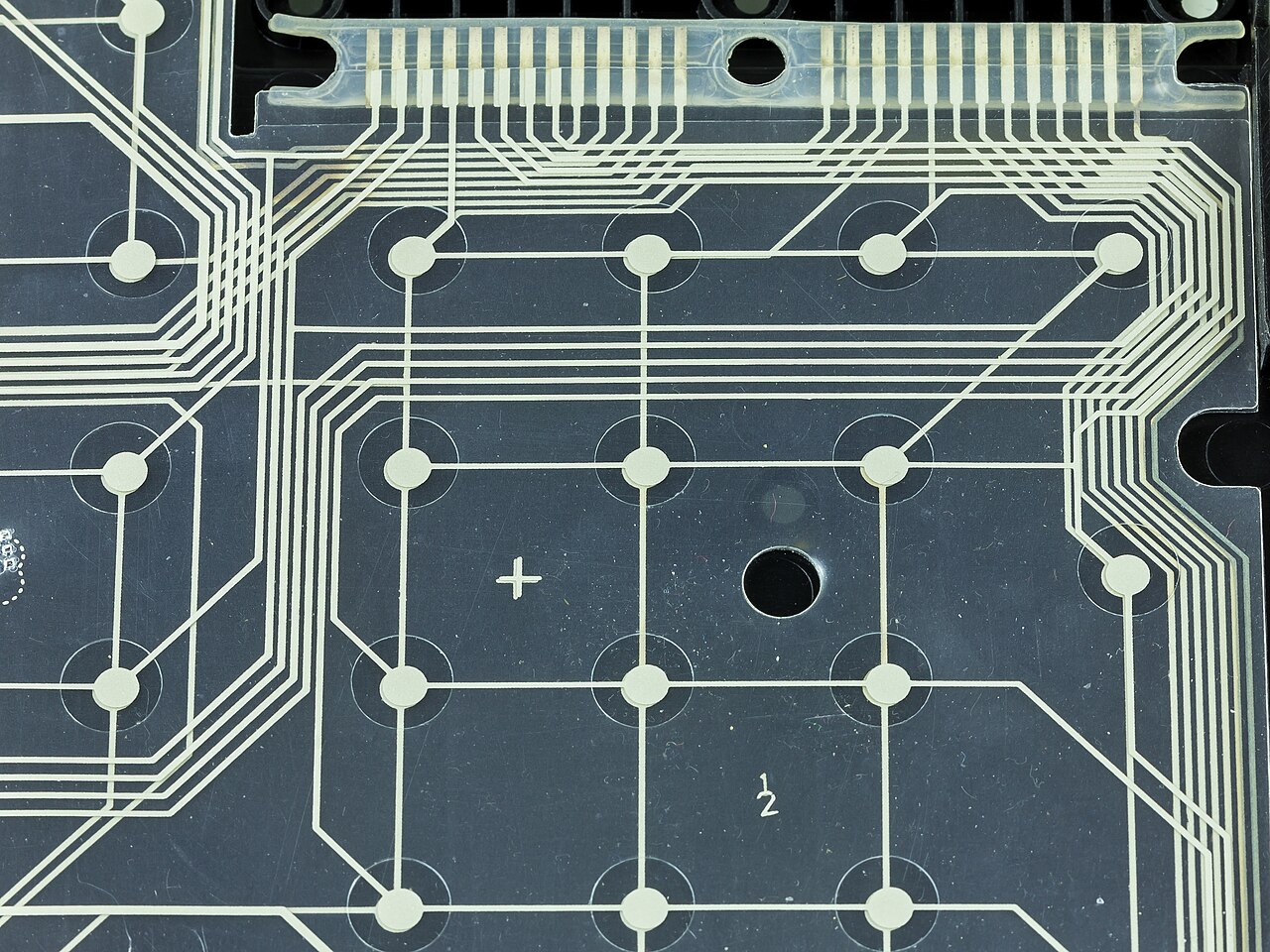
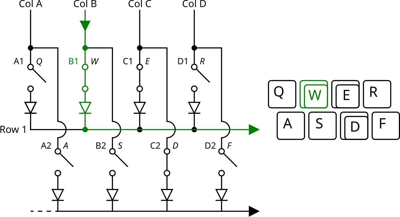
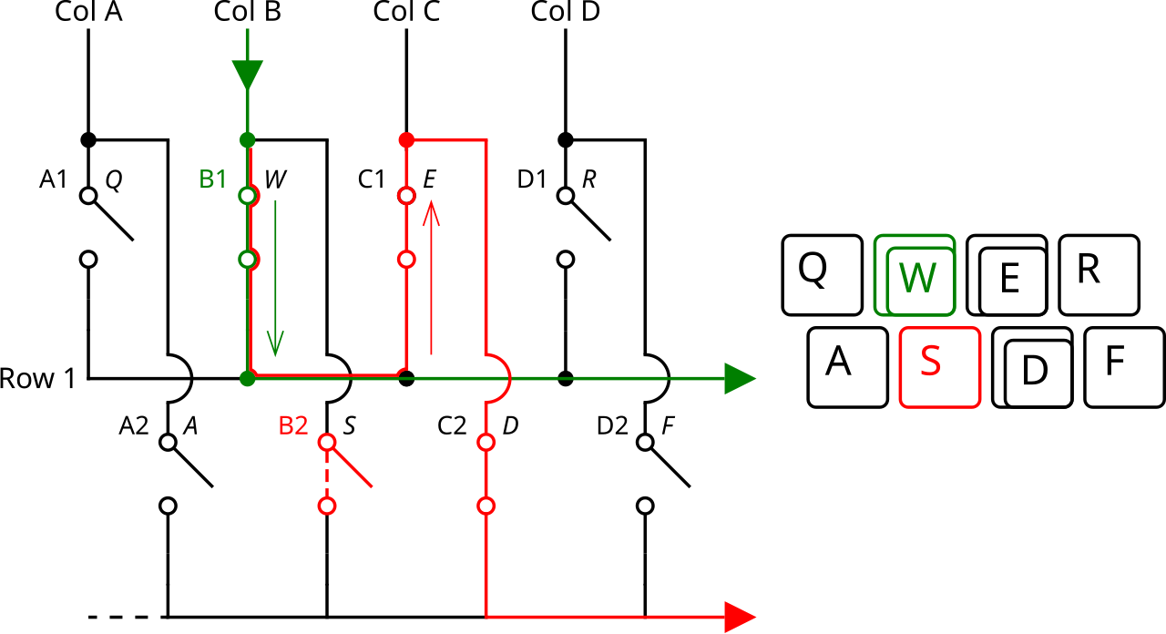
A keyboard matrix circuit connects key switches using a grid of wires, much like a diode matrix, and is common in electronic musical keyboards and computer keyboards. With 16 wires arranged into 8 rows and 8 columns, for example, up to 64 keys can be linked—enough to cover a full five-octave range of 61 notes. A keyboard controller scans the intersections of these wires to detect which keys are pressed. Without such a matrix, a 61-key digital piano or computer keyboard would need 62 wires (one per key plus a ground), creating a bulky wiring bundle. A matrix reduces this to just 16 wires. Schematically, it appears as 8 columns and 8 rows of wires with a switch at each crossing. The controller scans the columns; when a key is pressed, it scans the rows to find the row-column combination and generates the corresponding key code. This scanning happens so fast that the user notices no delay. This design has at least two drawbacks. First, it only provides a simple binary on/off signal for each key. Higher-quality musical keyboards use two slightly offset switch sets per key; by measuring the timing between their activation, the keyboard can determine key press velocity, greatly improving dynamic performance. Second, without a diode at each key crossing, instruments with a matrix circuit can only play monophonically. The diode prevents unwanted "phantom keys" from sounding or intended notes from being masked ("phantom key blocking"). Monophonic instruments and most low-cost computer keyboards omit most or all of these diodes to save money. To avoid "phantom keys", the keyboard controller in modern low-cost computer keyboards will ignore further key presses once two keys (other than modifier keys) have been pressed, which is known as key jamming or ghosting. Beyond musical keyboards and computer keyboards, matrix circuits appear in keypads (like those on calculators) and pinball machines. In pocket calculators, the multiplexed digit drive lines often double for keyboard scanning, providing additional savings.
- Wires without matrix
- 62
- Wires with matrix
- 16
- Rows
- 8
- Columns
- 8
- Keys connected
- 64
- Five octave range notes
- 61
Lore & Background
Without a matrix circuit, a 61-key keyboard might require 62 wires—an awkwardly thick bundle. With a matrix circuit, any of 61 keys can be determined with only 16 wires, drawn as 8 columns and 8 rows with a switch at every intersection. The keyboard controller scans columns; if a key is pressed, it scans rows to determine the row-column combination and generates the corresponding code, occurring so quickly the user is unaware of any delay. There are at least two limitations. First, it provides only a crude binary on/off signal; better electronic musical keyboards use two sets of switches per key, slightly offset, to determine velocity via timing between activations. Second, instruments with a matrix circuit can only play monophonically without a diode per key crossing to prevent phantom keys. Monophonic instruments and most low-cost computer keyboards reduce costs by omitting most or all diodes; to avoid "phantom keys", the keyboard controller in modern low-cost computer keyboards will ignore further key presses once two keys (other than modifier keys) have been pressed, which is known as key jamming or ghosting.
Reader's Guide
The keyboard matrix circuit is notable for drastically reducing wiring complexity in keyboards, from 62 wires to 16 for a 61-key layout. This efficiency enables compact and cost-effective designs in musical keyboards, computer keyboards, keypads (such as for calculators), and pinball machines. However, the article notes two key limitations: the binary on/off signal lacks velocity sensitivity, which better musical keyboards address with dual switches per key; and the need for diodes to support polyphonic operation, without which monophonic instruments and low-cost computer keyboards suffer from key jamming or ghosting. The approach also allows further savings in pocket calculators by using multiplexed digit drive lines to scan the keyboard. Its legacy is as a foundational wiring method that balances simplicity and functionality, though it imposes trade-offs in expressiveness and multi-key handling.
Did You Know?
- 16 wires arranged in 8 rows and 8 columns can connect 64 keys.
- Low-cost computer keyboards may ignore further key presses once two keys are pressed to avoid phantom keys, known as key jamming or ghosting.
- The matrix circuit approach is also used in keypads for calculators and pinball machines.
The Grid Architecture and Wire Economy
A keyboard matrix circuit represents a clever engineering solution to a fundamental wiring problem in electronic instruments and input devices. Without this approach, connecting a standard 61-key layout—enough to cover a full five-octave range on a digital piano or a typical computer keyboard—would demand roughly 62 individual conductors: one per key plus a shared ground line. That would produce an unwieldy, thick cable bundle that is impractical to manufacture and route. The matrix design sidesteps this by arranging wires into a grid, typically eight rows crossed by eight columns, yielding 64 intersection points. Each intersection hosts a key switch, and the total wire count drops to just 16. This is conceptually similar to a diode matrix, and the savings scale with the number of keys, making the architecture especially valuable as key counts grow. The result is a compact, manageable wiring harness that supports the full range of notes a performer or typist expects.
How the Controller Reads the Grid
Once the physical grid is in place, the keyboard controller takes over the task of translating a physical key press into a digital signal. The controller first sweeps through the column lines in sequence. If no key is depressed, every column reads as open and the scan moves on. The moment a closed circuit is detected on a column, the controller immediately shifts its attention to the row lines, probing each one until it finds the matching row. The intersection of that specific row and column pinpoints exactly which switch has been actuated, and the controller then outputs the corresponding key code. This two-stage column-then-row interrogation happens at a speed far beyond human perception, so a typist or pianist never experiences any noticeable lag between pressing a key and the system registering it. The elegance of the method lies in its sequential simplicity: rather than monitoring dozens of lines simultaneously, the controller needs only to check one axis at a time, dramatically reducing the processing burden while still delivering an unambiguous reading of every key in the matrix.
Velocity Detection and the Phantom Key Problem
The matrix architecture, while efficient, introduces two notable constraints that designers must address. First, each key crossing delivers only a basic binary signal—either the switch is closed or it is not. This means the controller cannot distinguish a gentle tap from a forceful strike. Higher-end electronic musical keyboards solve this by fitting two slightly offset switches beneath every key. By measuring the small time gap between the first and second switch closing, the system infers the velocity of the press, which in turn shapes the dynamic expression of the note produced. Second, without a dedicated diode at each grid intersection, pressing multiple keys simultaneously can create unintended current paths through the shared rows and columns. These spurious paths either trigger notes the player never touched (phantom keys) or mask notes that were deliberately pressed (phantom key blocking). Adding a diode per crossing prevents both problems and enables polyphonic performance, but it also adds cost and complexity, which is why many budget instruments omit them.
Beyond the Piano Bench
Although the matrix circuit is most commonly associated with electronic musical keyboards and standard computer keyboards, its reach extends well into other everyday devices. Calculator keypads, for instance, rely on the same row-and-column scanning principle to register button presses with a minimal number of traces. In pocket calculators, designers often repurpose the multiplexed digit-drive lines that already exist for the display to also scan the keypad, extracting additional wire savings without adding new circuitry. Pinball machines employ the same grid logic to track which buttons and switches have been activated during play. On the computer-keyboard side, manufacturers of low-cost models frequently skip most or all of the per-crossing diodes to keep production expenses down. To compensate for the resulting phantom-key risk, the firmware is programmed to stop registering additional key presses once two non-modifier keys are held down simultaneously—a behavior users commonly call key jamming or ghosting. This trade-off between hardware cost and input fidelity is a defining characteristic of budget keyboard design.
Gallery
Frequently Asked Questions
What is a Keyboard matrix circuit?
A keyboard matrix circuit is a grid of wires that links key switches together in rows and columns, allowing a controller to scan intersections and identify which keys are pressed. It is the standard wiring approach found in both computer keyboards and electronic musical keyboards.
How does a Keyboard matrix circuit work?
The circuit arranges wires into a row-and-column grid, and a keyboard controller scans the intersections to detect which specific key has been pressed. This scanning method replaces the need for a dedicated wire on every single key.
Why is a Keyboard matrix circuit important?
Without a matrix, a 61-key digital piano or computer keyboard would require 62 separate wires (one per key plus ground), resulting in a bulky and unwieldy wiring bundle. The matrix approach shrinks that to just 16 wires, making the design far more compact and practical.
How many wires does a typical Keyboard matrix circuit use?
A common configuration uses 16 wires total—8 rows and 8 columns—to connect up to 64 keys. This is enough to cover a full five-octave range of 61 notes found on standard keyboards.
How many keys can a Keyboard matrix circuit connect?
With 8 rows and 8 columns, a single matrix can link up to 64 key switches. This comfortably covers the 61 notes of a five-octave range, which is the standard layout for most computer and digital piano keyboards.
More in Computer Keyboards 1-24
Spotted an error? Know more?
Reader corrections go straight into our review queue. Suggest an edit · How this site is sourced