Telegraph code
Character encodings for telegraphy, from optical to electrical systems.
A telegraph code is a system for turning letters, numbers, and other characters into signals that can be sent by telegraphy. The most famous example is Morse code. While "telegraphy" usually means the electric kind, optical telegraph systems—using towers and visible signals—came first. Every code is built from code points, with one code point assigned to each letter, digit, or symbol.
Codes meant for people to read were designed so that common letters used the shortest code points. In Morse code, for instance, the letter E (the most frequent in English) is a single dot, while Q is much longer. This let operators send messages faster and tire less easily. Until the late 1800s, humans always ran the telegraphs. When automated machines arrived, variable-length codes like Morse were awkward to build into the hardware. So fixed-length codes became standard. The first was Baudot, a five-bit code that could only print uppercase letters. Later codes added more bits—ASCII used seven, allowing both uppercase and lowercase. Today’s computers need huge code spaces: Unicode uses 21 bits to handle many languages without switching encodings. Modern machines easily manage variable-length codes like UTF-8 and UTF-16, which are now everywhere.
**Manual telegraph codes** Before the electric telegraph, many countries built national networks using optical telegraphs—chains of towers that passed signals by semaphore or shutters. France developed this most heavily, starting during the French Revolution. The French code was the Chappe code, named after its inventor Claude Chappe. Britain’s Admiralty used its own semaphore code, which had to differ because the British system worked differently: Chappe’s used movable arms (like flag semaphore), while the British used an array of shutters that opened or closed.
**Chappe code** The Chappe system had a large pivoted beam (the regulator) with an arm (indicator) at each end, each pivoting around the regulator. Allowed angles were multiples of 45° for clarity. This gave 8×4×8 possible positions, but the indicator aligned with the regulator was never used (it looked like the indicator folded back), leaving 98 code points. Symbols always used the regulator on a left or right diagonal; only left-diagonal positions were for messages, while right-diagonal positions controlled the system.
- Earliest known use
- 1793
- First operational network
- Paris to Lille, 1794
- Code space of chappe system
- 98 code points
- Text code points in chappe system
- 94 or 92
- Edelcrantz codebook size
- 5,120 codepoints
- Myer code type
- ternary code
Lore & Background
Prior to the electrical telegraph, a widely used method of building national telegraph networks was the optical telegraph consisting of a chain of towers from which signals could be sent by semaphore or shutters from tower to tower. This was particularly highly developed in France and had its beginnings during the French Revolution. The code used in France was the Chappe code, named after Claude Chappe the inventor. The British Admiralty also used the semaphore telegraph, but with their own code. The British code was necessarily different from that used in France because the British optical telegraph worked in a different way. The Chappe system had moveable arms, as if it were waving flags as in flag semaphore. The British system used an array of shutters that could be opened or closed.
The Chappe system consisted of a large pivoted beam (the regulator) with an arm at each end (the indicators) which pivoted around the regulator on one extremity. The angles these components were allowed to take was limited to multiples of 45° to aid readability. This gave a code space of 8×4×8 code points, but the indicator position inline with the regulator was never used because it was hard to distinguish from the indicator being folded back on top of the regulator, leaving a code space of 98. Symbols were always formed with the regulator on either the left- or right-leaning diagonal (oblique) and only accepted as valid when the regulator moved to either the vertical or horizontal position. The left oblique was always used for messages, with the right oblique being used for control of the system. This further reduced the code space to 98, of which either four or six code points (depending on version) were control characters, leaving a code space for text of 94 or 92 respectively.
The Edelcrantz system was used in Sweden and was the second largest network built after that of France. The telegraph consisted of a set of ten shutters. Nine of these were arranged in a 3×3 matrix. Each column of shutters represented a binary-coded octal digit with a closed shutter representing '1' and the most significant digit at the bottom. Each symbol of telegraph transmission was thus a three-digit octal number. The tenth shutter was an extra-large one at the top. Its meaning was that the codepoint should be preceded by 'A'.
Reader's Guide
Telegraph codes evolved from human-operated optical systems to machine-readable electrical codes. Codes meant for human interpretation were designed so that the characters that occurred most often had the fewest elements in the corresponding code point, allowing messages to be sent more quickly and reducing operator fatigue. When automated telegraph messages came in, codes with variable-length code points were inconvenient for machine design of the period. Instead, codes with a fixed length were used. The first of these was the Baudot code, a five-bit code. Baudot has only enough code points to print in upper case. Later codes had more bits (ASCII has seven) so that both upper and lower case could be printed. Beyond the telegraph age, modern computers require a very large number of code points (Unicode has 21 bits) so that multiple languages and alphabets can be handled without having to change the character encoding. Modern computers can easily handle variable-length codes such as UTF-8 and UTF-16 which have now become ubiquitous. The legacy of telegraph codes is seen in the fixed-length and variable-length encodings that underpin all digital communication.
Did You Know?
- The Chappe code used a code book with 94 pages and 94 entries per page, allowing an entire sentence to be sent with just two symbols.
- The Edelcrantz system used a tenth shutter to indicate that a codepoint should be preceded by 'A', enabling a codebook of predetermined messages.
- Albert J. Myer's wig-wag code used a ternary system with three distinct flag positions, though alphabetical codepoints required only two positions.
- American Morse code had about five elements, rather than the two (dot and dash) of International Morse Code.
Origins and a Century-and-a-Half of Refinement
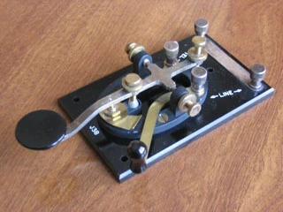
The telegraph key traces its lineage to Alfred Vail, a collaborator of Samuel Morse, who crafted the very first version of this specialized electrical switch. Since that pioneering moment, the device has undergone more than a century and a half of refinement across numerous countries, spawning an entire community of devoted collectors. One of the most fascinating early divergences was purely cultural: American operators favored keys with short, flat-topped knobs and narrow, often curved bars, while their European counterparts preferred tall, ball-shaped knobs mounted on thick bars. Despite the functional equivalence of both styles, practitioners on each side of the Atlantic developed fierce loyalty to their own tradition. The straight key itself operates on a deceptively simple principle—a bar pressed against spring tension to close an electrical circuit—yet this basic mechanism has persisted in period films and television shows as the iconic image of telegraphy, used in both landline and radio systems to transmit the short pulses called dots or dits and the longer pulses called dashes or dahs that encode letters and characters.
The Railroad Shorting Bar and System Wiring
A distinctive feature of straight keys built for American railroad telegraphy was the inclusion of a shorting bar, a component rooted in the specific wiring philosophy of North American rail networks. In those systems, signal power was drawn from batteries housed only at one or both ends of a line in telegraph offices, rather than each individual station maintaining its own battery bank as was common in Europe. When an operator was not actively sending, the shorting bar completed the electrical path through the station, allowing sounders at all downstream stations to respond to signals traveling down the line. This meant an operator in the next town could still receive a message originating from the central office even while the local key sat idle. The shorting bar became so embedded in tradition that it occasionally appeared on later key models, though it served no practical purpose in radio telegraphy. Its one modern convenience was allowing an operator to leave a steady signal running for transmitter tuning, freeing both hands to adjust equipment rather than resorting to the inelegant practice of plopping a book on top of the key.
Speed, Strain, and the Operator's Body
The physical demands of operating a straight key were considerable. Novice operators typically managed around five words per minute, roughly twenty-five characters, while skilled practitioners could push toward thirty words per minute, or about one hundred and fifty characters. However, the rapid pumping motion required to produce a sustained string of dots took a serious toll on the body. In the early era of telegraphy, numerous professional operators developed a repetitive stress injury colloquially known as glass arm or telegrapher's paralysis. One partial remedy was loosening the adjustable trunnion screws to increase the side play of the key, reducing the precision of wrist motion demanded by each stroke. Better manual technique or switching to a side-to-side key design could avoid the problem entirely. The up-and-down pounding motion, which operators called pounding brass, engaged a different set of muscles than the lateral swings of alternative keys, making the choice of key design not merely a matter of preference but a genuine health consideration for those spending long hours at the instrument.
From Sideswipers to Electronic Keyers
The quest for greater speed and reduced physical strain drove a long lineage of alternative key designs. The first widely adopted departure from the up-and-down straight key was the sideswiper, also called a sidewinder, cootie key, or bushwhacker. Its lever swung laterally with contacts on both sides and a spring-loaded arm returning to center, letting the operator produce a dit or dah by swinging in either direction and a rapid series of dits by thrashing the arm back and forth. This motion introduced a distinctive rhythmic swing that noticeably shaped the operator's transmission rhythm, known as fist. A step further was the semi-automatic key, popularly called a bug after the Vibroplex brand that popularized it. Its clockwork-style pendulum mechanism rocked against a contact point to produce uniformly timed dits, reducing hand motion and enabling speeds exceeding forty words per minute. From the mid-twentieth century onward, electronic keyers replaced these mechanical systems, operated through single-paddle or double-paddle iambic squeeze keys, with the circuitry either standing as an independent device or built directly into modern amateur radios.
Frequently Asked Questions
What is Telegraph code?
A telegraph code is a signaling system that converts letters, digits, and symbols into transmittable signals for long-distance communication. The best-known example is Morse code, though the concept predates electrical systems entirely.
When was Telegraph code first used?
The earliest known use of a telegraph code dates to 1793, when optical tower systems began encoding messages with visible signals. The first fully operational network connected Paris to Lille in 1794.
How does Telegraph code assign signals to characters?
Each letter, digit, or symbol is mapped to a unique code point within the system's overall code space. Codes built for human readability typically give the most frequent characters the shortest signals, as in Morse code where E is a single dot while Q requires many more elements.
How large is the code space of major Telegraph code systems?
Chappe's optical system allocated 98 code points, of which 94 or 92 were dedicated to text characters. The Edelcrantz codebook, by contrast, contained 5,120 code points to support a far larger vocabulary.
What types of Telegraph code exist beyond simple binary?
Not every telegraph code relies on two states; the Myer code, for example, is a ternary system that uses three distinct signal levels. This shows that telegraph encoding evolved well beyond basic on/off patterns.
More in Telegraph Keys and Codes 1-24
Spotted an error? Know more?
Reader corrections go straight into our review queue. Suggest an edit · How this site is sourced