Transmission line
A structure designed to conduct electromagnetic waves with minimal reflections and losses.
Last updated

Thebezaliel · CC BY-SA 3.0
A transmission line is a specialized cable or other structure designed to conduct electromagnetic waves in a contained manner. The term applies when the conductors are long enough that the wave nature of the transmission must be taken into account, which is especially relevant in radio-frequency engineering because short wavelengths cause wave phenomena to arise over very short distances.
Quick Facts
- Characteristic impedance coaxial
- 50 Ω
- Characteristic impedance twisted pair
- 100 Ω
- Characteristic impedance untwisted pair
- 300 Ω
- Typical propagation delay range
- 4 ns/m to 5 ns/m
Facts from the source article.
Lore & Background
The mathematical analysis of transmission lines grew from the work of James Clerk Maxwell, Lord Kelvin, and Oliver Heaviside. In 1855, Lord Kelvin formulated a diffusion model of current in a submarine cable, which correctly predicted the poor performance of the 1858 trans-Atlantic submarine telegraph cable. In 1885, Heaviside published the first papers describing his analysis of propagation in cables and the modern form of the telegrapher's equations.
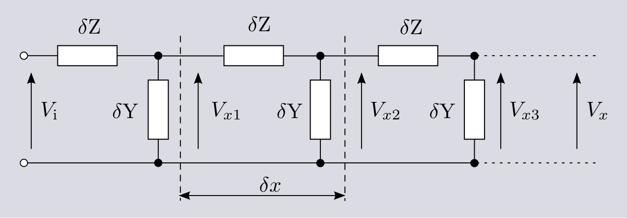
Transmission lines are used for connecting radio transmitters and receivers with their antennas (as feed lines or feeders), distributing cable television signals, trunklines routing calls between telephone switching centres, computer network connections, and high-speed computer data buses. RF engineers commonly use short pieces of transmission line in the form of printed planar transmission lines to build distributed-element circuits such as filters, as an alternative to circuits using discrete capacitors and inductors.
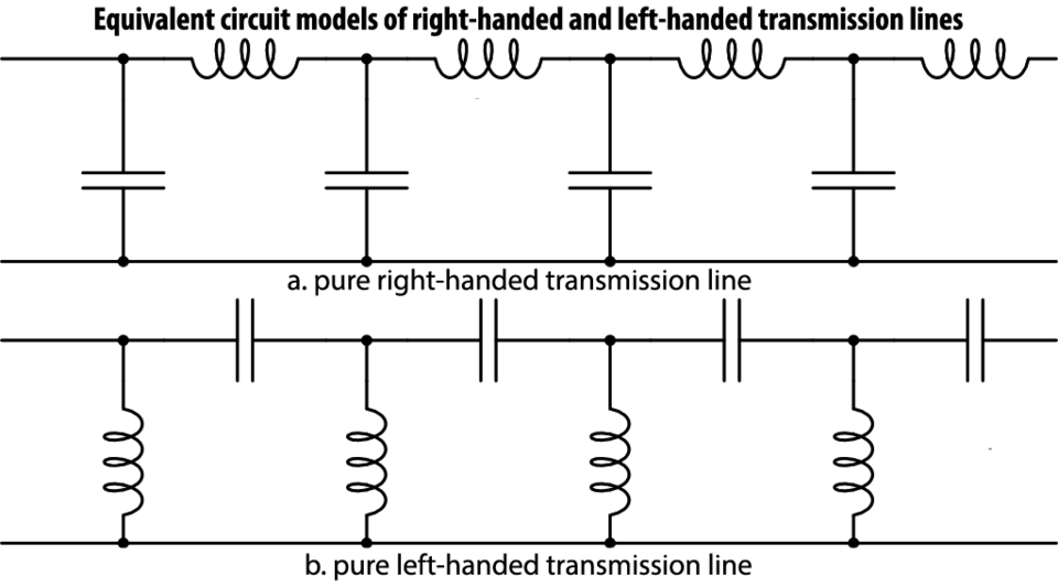
Types of transmission line include parallel line (ladder line, twisted pair), coaxial cable, and planar transmission lines such as stripline and microstrip. At microwave frequencies and higher, power losses in transmission lines become excessive, and waveguides are used instead, which function as pipes to confine and guide electromagnetic waves.
Purpose and Design Philosophy
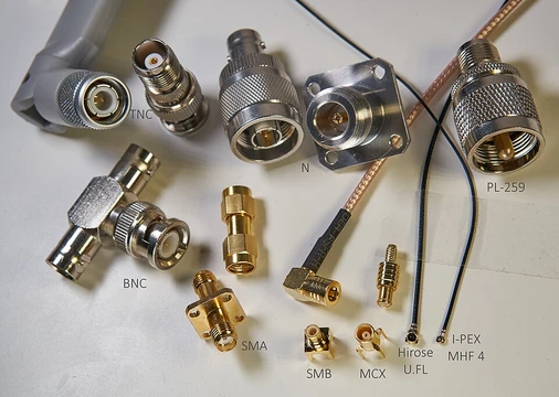
RF connectors serve as the critical junction points in radio frequency circuits, engineered to operate reliably across the multi-megahertz spectrum. Their primary role is to join coaxial cables while preserving the electromagnetic shielding that the coaxial geometry provides.
Beyond mere physical connection, well-designed RF connectors work to minimize impedance discontinuities at the joint, which directly reduces signal reflection and associated power loss. This impedance-matching consideration becomes increasingly critical as operating frequencies climb, because even minor variations in transmission line impedance at a connector can cause a meaningful portion of the signal to bounce back rather than continue forward. Additionally, a properly constructed RF connector must act as a barrier against external electromagnetic interference and capacitive pickup, ensuring that stray signals from the environment do not leak into the circuit and corrupt the intended signal path.

Mechanical Engineering and Durability
The mechanical design of an RF connector balances several competing demands. Fastening mechanisms vary widely—threaded couplings, bayonet latches, brace systems, and blind-mate interfaces each serve different mounting and serviceability needs.
Equally important is the electrical contact design: many connectors incorporate spring elements that maintain a low-resistance ohmic connection while protecting the gold-plated contact surfaces from excessive wear. This approach allows the connector to endure very high numbers of mating and demating cycles without degrading performance, all while keeping the insertion force manageable for the technician or automated assembly line. The interplay between mechanical robustness, electrical continuity, and surface protection represents a significant engineering challenge, particularly when the connector must function reliably at frequencies where even nanometer-scale gaps or misalignments can disrupt the signal path.
Frequency-Dependent Performance Challenges
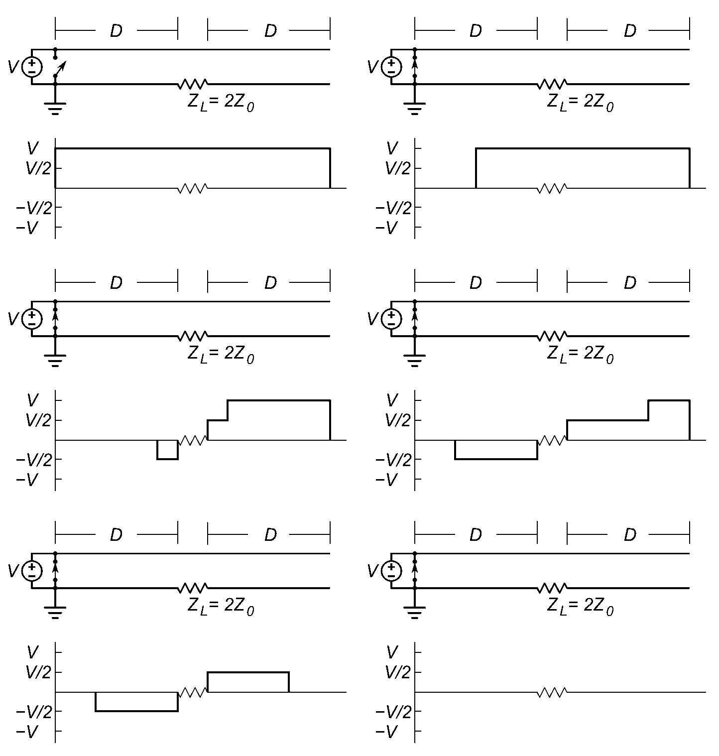
As the operating frequency of a circuit rises, the behavior of the connection point shifts from a simple lumped-element junction to a full transmission line problem. At these elevated frequencies, small impedance variations introduced by the connector geometry—changes in conductor spacing, dielectric discontinuities, or mechanical tolerances—become electrically significant.
The result is that a portion of the signal energy reflects at the junction rather than transmitting through, degrading both signal integrity and power delivery. Compounding this, the connector must simultaneously prevent external electromagnetic fields from coupling into the circuit and block capacitive pickup of stray signals. These dual requirements—maintaining internal signal fidelity while rejecting external interference—make RF connector design a delicate balancing act that grows more demanding with each increment in frequency.
Applications and Market-Driven Innovation
RF connectors find their way into a remarkably diverse set of systems. They appear in consumer television receivers, two-way radio equipment, Wi-Fi PCIe cards that feature removable antennas, and the industrial and scientific measurement instruments that rely on radio frequency signals for their operation.
The sheer breadth of these applications reflects how fundamental the connector is to any system that must transmit or receive energy at radio frequencies. On the research side, the early 2000s witnessed a notable acceleration in radio-frequency circuit design activity, propelled by the enormous commercial appetite for affordable, high-data-rate wireless transceivers. This market pressure accelerated innovation in connector design, pushing engineers to deliver better impedance matching, higher mating-cycle endurance, and lower insertion loss at cost points that mass-market products could sustain.
Reader's Guide
Transmission lines are fundamental to radio-frequency engineering because ordinary cables are not suitable for carrying currents above about 30 kHz, as energy tends to radiate as radio waves and reflections from discontinuities cause power losses. The distinguishing feature of most transmission lines is uniform cross-sectional dimensions along their length, giving a uniform characteristic impedance that prevents reflections. For analysis, a transmission line can be modelled as a two-port network; when the load impedance equals the characteristic impedance, the line is said to be matched, and maximum power is absorbed by the load with minimal reflection.
Power loss in a transmission line arises from ohmic (resistive) loss and, at high frequencies, dielectric loss caused by the insulating material absorbing energy from the alternating electric field. Total loss is often specified in decibels per metre and depends on frequency. The telegrapher's equations, developed by Oliver Heaviside based on Maxwell's equations, describe voltage and current on a transmission line using a distributed-element model with series resistance and inductance, and shunt capacitance and conductance per unit length. In the special case of a lossless line, the resistance and conductance are negligibly small.
Did You Know?
- A loss of 3 dB corresponds approximately to a halving of the power.
- Propagation delay is never less than the length divided by the speed of light.
- Transmission lines become necessary when the transmitted frequency's wavelength is sufficiently short that the cable length becomes a significant part of a wavelength.
Frequently Asked Questions
Who is Transmission line?
Transmission line is a purpose-built cable or structure whose job is to guide electromagnetic waves along a contained path. The label only applies once the conductors are long enough that the wave behavior of the signal can no longer be ignored.
What is Transmission line's signature stat (characteristic impedance)?
A standard coaxial variant sits at 50 Ω, a twisted-pair variant at 100 Ω, and an untwisted pair at 300 Ω. Matching a source or load to that value is what keeps unwanted reflections under control.
How fast does a signal travel through Transmission line?
Propagation delay typically falls between 4 and 5 nanoseconds per meter, depending on the dielectric material inside. That means every meter of run adds roughly 4–5 ns of latency to the signal.
More in RF Connectors and Coax
Sources
Compiled from Wikipedia and the sources listed below. Text from Wikipedia is available under CC BY-SA 4.0; this entry is adapted from it.
- Wikipedia: Transmission line (CC BY-SA 4.0).
- Word definitions: the Codexery glossary, each quoted from its Wikipedia article.
Spotted an error? Know more?
Reader corrections go straight into our review queue. Suggest an edit · How this site is sourced