
Technical drawing
Technical drawing communicates function and construction through precise visual language.

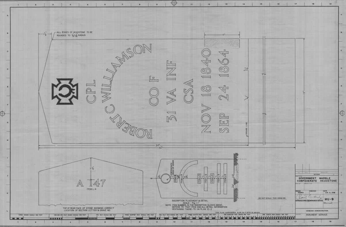
Veterans Administration · Public domain
Technical drawing, also called drafting, is the practice of creating drawings that show how something works or is built. It is a key tool for sharing ideas in engineering and industry. To make these drawings clear, drafters use standard symbols, viewpoints, measurement units, notation, visual styles, and page layouts. These conventions form a visual language that makes the drawing easy to understand and leaves little room for confusion. Many of these symbols and rules are set out in an international standard known as ISO 128.
The need for precise communication sets technical drawing apart from artistic drawing. Artistic drawings are open to personal interpretation and can have many meanings. Technical drawings are meant to have only one intended meaning. A person who makes any kind of drawing is called a drafter. A professional who specializes in technical drawings is sometimes called a drafting technician.
**Methods**
**Sketching** A sketch is a quick, freehand drawing, usually not meant as a finished piece. It is a fast way to record an idea for later use. Architects, for example, use sketches to try out different ideas and plan a composition before creating a more detailed and time-consuming final work. Architectural sketches are a type of diagram. Like metaphors, they help architects communicate and work together on designs. This tool lets architects pull out key features of possible design solutions and simplify complex patterns, which improves the design process.
**Manual or by instrument** The basic manual drafting process starts with placing paper on a smooth surface with straight sides and right-angle corners—usually a drawing board. A T-square, a sliding straightedge, is set against one side of the board and can slide across the paper. Moving the T-square and running a pencil or technical pen along its edge draws parallel lines. The T-square also holds other tools, like set squares or triangles. By placing a triangle of a known angle on the T-square (which is already at a right angle to the board’s edge), the drafter can draw lines at any chosen angle. Modern drafting tables use a drafting machine supported on both sides, which slides over large paper. Because it is secured on both sides, lines drawn along its edge are always parallel.
Drafters use several tools for curves and circles. Compasses draw arcs and circles, and French curves draw curved lines. A spline is a flexible, rubber-coated metal rod that can be bent by hand to form most curves. Drafting templates help by providing pre-made shapes for common symbols, so the drafter does not have to draw them from scratch each time. For example, a lighting designer in stagecraft uses a template with standard USITT lighting fixture symbols to show where a common fixture goes in different positions. Templates are sold by many vendors and are often customized for specific tasks, but drafters also sometimes make their own.
This manual system requires an accurate table and constant care in positioning tools. Even simple tasks, like drawing two angled lines that meet at a point, need several moves of the T-square and triangles. Drafting can be a slow process. The mechanical drafting machine, a type of pantograph (sometimes wrongly called a "pentagraph"), solved these problems. It gave the drafter a precise right angle anywhere on the page quickly. Many of these machines could also change the angle, removing the need for triangles.
Beyond the mechanics of drawing lines, arcs, circles, and text on paper, drafting requires a solid understanding of geometry, trigonometry, and spatial thinking. It demands high precision, accuracy, and close attention to detail. Although a project engineer, architect, or shop worker (like a machinist) sometimes does drafting, skilled drafters or designers usually handle the task, and they are always in demand.
**Computer aided design** Today, much of the drafting work has been automated and sped up by computer-aided design (CAD) systems. There are two main types: 2D and 3D. 2D CAD systems, such as AutoCAD or MicroStation, replace the paper drawing board. Lines, circles, arcs, and curves are created inside the software. The user’s technical drawing skill still determines the quality of the result. Errors can still happen when making orthographic projections, auxiliary views, and cross-sections. A 2D CAD system is basically an electronic drawing board. Its biggest advantage over hand drawing is in making changes. In a hand-drawn technical drawing, finding a mistake or needing a change means starting a new drawing from scratch. A 2D CAD system allows the drafter to edit the existing drawing directly.
- field
- Technical drawing, drafting
- known_for
- Visual communication of function and construction in industry and engineering
- methods
- Sketching, manual or by instrument, computer-aided design (CAD)
- practitioners
- Drafters, drafting technicians, architects, engineers
Lore & Background
Technical drawing distinguishes itself from expressive artistic drawing by its need for precise communication in preparing a functional document. Artistic drawings are subjectively interpreted with multiple meanings, while technical drawings are understood to have one intended meaning. A drafter is a person who makes a drawing, and a professional drafter who makes technical drawings is sometimes called a drafting technician.
Reader's Guide
The methods of technical drawing have evolved from sketching and manual instrument-based drafting to computer-aided design (CAD). Sketching is a quick, freehand way to record ideas, often used by architects to try out different designs. Manual drafting uses tools such as T-squares, set squares, compasses, French curves, splines, and drafting templates on a drawing board, requiring precision and attention to detail. The introduction of the mechanical drafting machine, an application of the pantograph, allowed drafters to quickly produce accurate right angles at any point on the page. Today, 2D CAD systems like AutoCAD replace the paper drawing discipline, allowing easy revisions, while 3D CAD systems such as SolidWorks generate technical drawings from user-defined views of a part's geometry, reducing scope for error. Technical drawing finds applications in architecture, where detail drawings and plans communicate an architect's design, and in engineering, where drawings accurately capture geometric features of a product or component for manufacture.
Did You Know?
- A professional drafter who makes technical drawings is sometimes called a drafting technician.
- The basic drafting procedure uses a T-square placed on a drawing board to draw parallel lines.
- 3D CAD systems allow individual parts to be assembled together to represent the final product before technical drawings are released for manufacture.
The Architecture of an Engineering Drawing
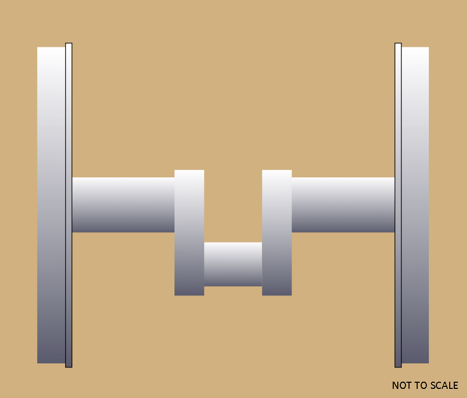
An engineering drawing is far more than a single sketch. A complete specification for even a modest component typically requires multiple drawings, all cross-referenced through what is commonly called an assembly drawing. This master document lists the drawing numbers of each detailed component, the quantities needed, the construction materials involved, and sometimes three-dimensional images to help locate individual parts. Within each individual detail drawing, designers present multiple orthographic views of the part, occasionally adding scratch views to clarify tricky details. Dimensions are deliberately placed in only one location to prevent redundancy and the risk of contradictory information. Critical dimensions carry tolerances that ensure the part can actually be manufactured and function as intended. Beyond the pictographic geometry, the drawing relies on a shared vocabulary of abbreviations and symbols for brevity, supplemented by textual notes where needed. Every drawing carries a title block—an information box recording who drew it, who approved it, the units used, the meaning of each view, the drawing's title, and its unique number.
From Military Secret to Industrial Revolution
Technical drawing as a practice stretches back to antiquity, and the Renaissance produced extraordinary examples such as the notebooks of Leonardo da Vinci. Yet the modern discipline—governed by precise conventions of orthographic projection and scale—emerged in France during the early stirrings of the Industrial Revolution. The key figure was Gaspard Monge of Mezieres, who in 1765 developed the method of representing three-dimensional objects on a two-dimensional plane. Crucially, this knowledge was locked away as a military secret until 1794, which meant it remained entirely unknown in England for nearly three decades. When Marc Isambard Brunel produced his drawings of block-making machinery in 1799, he had clearly mastered this newly available technique. As L. T. C. Rolt observed in his biography of Marc's son, Isambard Kingdom Brunel, those drawings likely contributed more to British engineering practice than the machines themselves ever did, because they embodied a systematic way of communicating complex geometry that had only just crossed the Channel.
A Universal Language Through Standards
Because engineering drawings must specify requirements that can be extremely complex, a shared set of rules governs both how they are written and how they are read. This standardization serves a critical international purpose: an engineer in one country can interpret a drawing produced in another, regardless of spoken language, because the symbols and conventions carry the meaning. In the United States, the dominant framework is ASME Y14.5 and its metric counterpart Y14.5M, most recently revised in 2018. That same year, ASME AED-1 was introduced to address advanced practices in aerospace and related industries, supplementing the Y14.5 family. On the international side, ISO 8015 sets out the fundamentals of geometrical product specifications. A 2011 revision introduced the Invocation Principle: once any part of the ISO GPS system appears in a mechanical product document, the entire ISO GPS framework is automatically invoked. Marking a drawing with the phrase Tolerancing ISO 8015 is optional, but the implication is clear—any drawing using ISO symbols must be interpreted under ISO GPS rules unless a national standard is explicitly invoked. Britain's BS 8888 has also seen significant updates during the 2010s.
From Pencil to Pixel
For centuries, every engineering drawing was produced by hand—pencil and pen working on paper, vellum, or mylar. The drafter's toolkit included straightedges, T-squares, French curves, triangles, protractors, dividers, compasses, scales, erasers, push pins, and a drafting board or table. Slide rules once belonged in that collection, though even today's occasional manual drafter now reaches for a pocket calculator instead. Integrated drafting machines combined boards, straightedges, and pantographs into a single workstation. The English idiom to go back to the drawing board was born from the literal experience of spotting a design error mid-production and returning to the board to revise the drawing. Reproduction of the original typically yielded blue-and-white copies, which is why the term blueprint endured long after inkjet and laser printers made black or multicolour lines on white paper the norm. In the United States, the generic word print now covers any paper copy of a drawing. Since the 1970s, computer-aided design has steadily displaced manual methods, and today most engineering drawing is done electronically, though pencil and paper have not vanished entirely.
Gallery
Frequently Asked Questions
Who is Technical drawing?
Technical drawing is the discipline of producing precise visual representations that show how a component operates or how a structure fits together. It acts as the shared visual language connecting engineers, architects, and drafters throughout the industry.
What are Technical drawing's powers or role?
Its core function is turning complex mechanical or structural ideas into unambiguous visual instructions built from standardized symbols, projected views, and measurement notations. This guarantees that every reader—regardless of location or background—interprets the design identically.
How does Technical drawing's story end?
A drawing's arc concludes once the final approved sheet (or CAD file) is released to fabrication, at which point it becomes the single authoritative reference for building the object. From that moment the drawing shifts from a design tool to a permanent construction record.
Why is Technical drawing important?
Without it, engineers and fabricators would lack a universal, reliable way to convey exact dimensions, tolerances, and assembly sequences. It removes guesswork and keeps every stakeholder locked onto one precise interpretation of the design.
More in Construction And Engineering 1-18
Spotted an error? Know more?
This is a living reference — every entry is fact-audited, and reader corrections feed straight into our audit queue. Suggest an edit · See this site's audit record