Wattmeter
Instrument for measuring electric active power in watts.
Last updated

Alej27 · CC BY-SA 4.0
A wattmeter measures the electric active power (the average rate of electrical energy flow) in watts for any circuit. Electromagnetic wattmeters handle utility and audio frequency power, while radio frequency measurements require different types.
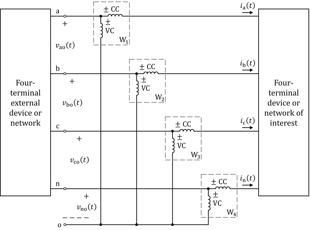
Electrodynamic
The device reads the average value of the product of instantaneous voltage and current, which in sinusoidal steady-state equals the root-mean-square voltage times root-mean-square current times the cosine of the phase angle between them.
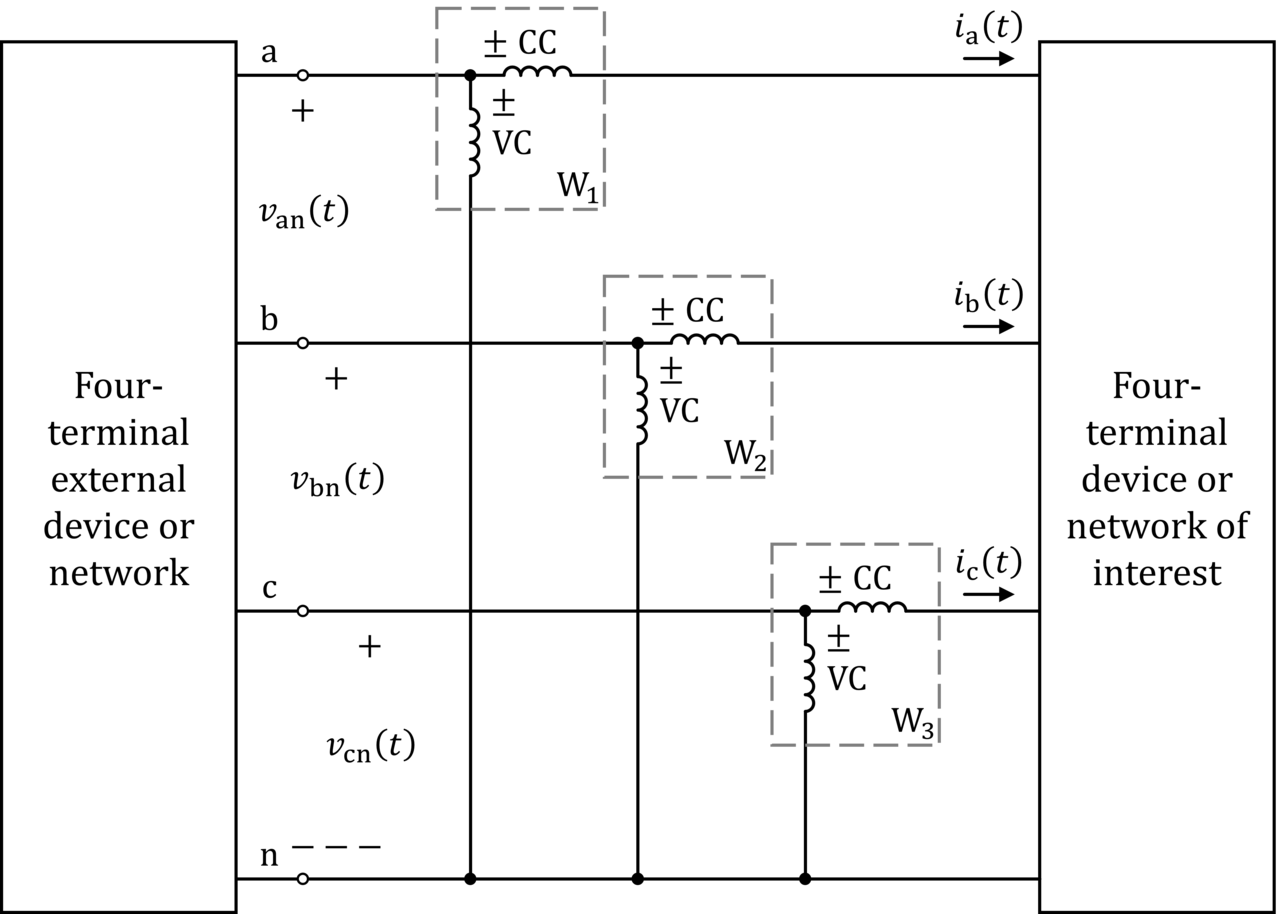
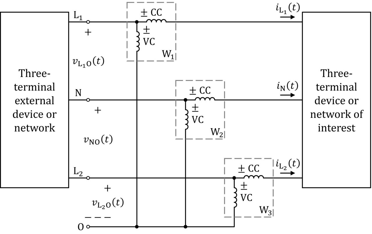
The traditional analog wattmeter is an electrodynamic instrument. It has a pair of fixed current coils connected in series with the circuit and a movable potential coil connected in parallel. The potential coil carries a needle that moves over a scale. A current through the current coils creates an electromagnetic field proportional to and in phase with the line current.
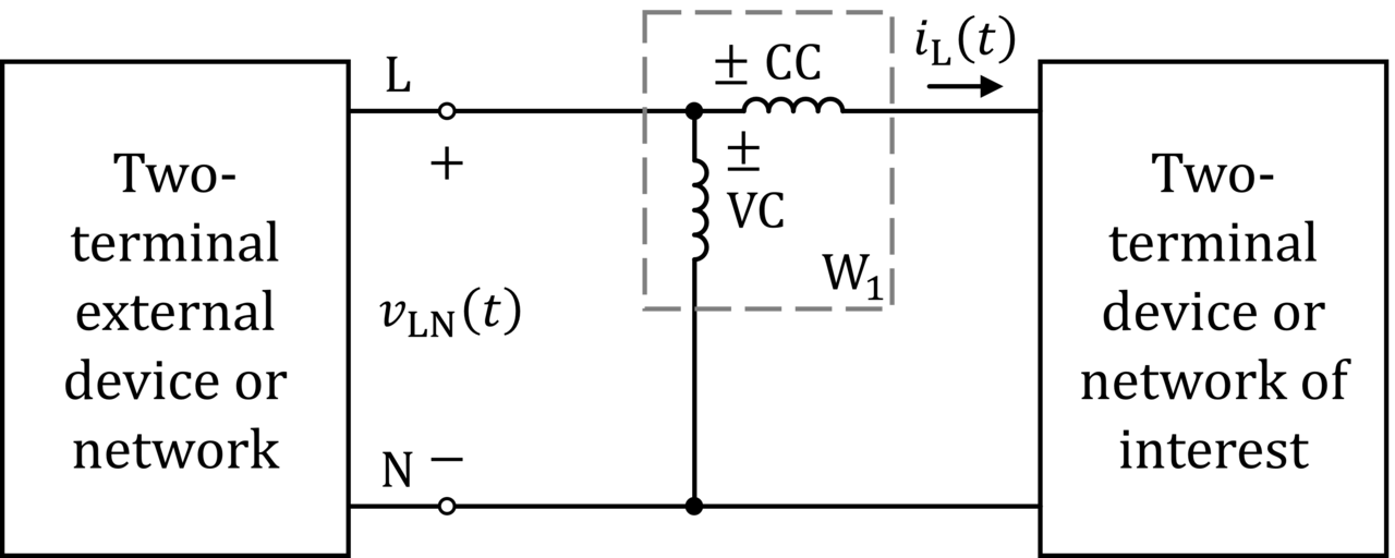
The potential coil typically has a high-value resistor in series to limit its current. On a DC circuit, the needle deflection is proportional to both current and voltage, following P=VI. On an AC circuit, deflection is proportional to the average instantaneous product of voltage and current, measuring active power as P=VI cos φ, where cos φ is the power factor.
Electronic
Electronic wattmeters are used for direct small power measurements or for frequencies beyond the range of electrodynamic types.
Digital
A modern digital wattmeter samples voltage and current thousands of times per second, multiplying each voltage sample by the corresponding current sample and averaging over at least one cycle to get real power. A computer circuit calculates RMS voltage, RMS current, apparent power (VA), real power (watts), power factor, and kilowatt-hours.
Readings may be displayed, logged, or transmitted. Accuracy varies, especially when real power is much lower than VA (highly reactive loads) or when waveforms are non-sinusoidal, as with switched-mode power supplies. Simple meters may only be accurate for sinusoidal waveforms.
Precision and accuracy
Inexpensive wattmeters have limitations, particularly for low power (under 10 watts), where readings may be inaccurate. This is largely due to difficulty measuring alternating current accurately. A typical plug-in meter may specify error as ±5% of measured value ±10 W for wattage and ±5% ±0.1 kW·h for energy. For a 5 W laptop in sleep mode, the meter could read anywhere from 0 to 15.25 W, not counting waveform errors.
Quick Facts
- Inventor
- Ottó Bláthy
- Patent year
- 1974
- Patent holders
- Maghar S. Chana
- Ramond L. Kraley
- Eric A. Hauptmann Barry
- M. Pressman
Facts from the source article.
Lore & Background
The traditional analog wattmeter is an electrodynamic instrument consisting of a pair of fixed current coils and a movable potential coil. The current coils are connected in series with the circuit, while the potential coil is connected in parallel and carries a needle that moves over a scale. On DC circuits, the deflection is proportional to both current and voltage, conforming to P=VI. On AC circuits, the deflection is proportional to the average instantaneous product of voltage and current, measuring active power P=VI cos φ.
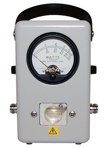
Electronic wattmeters are used for direct small power measurements or at frequencies beyond the range of electrodynamometer-type instruments. A modern digital wattmeter samples voltage and current thousands of times per second, multiplying each sample to calculate real power, RMS voltage, RMS current, VA, power factor, and kilowatt-hours. At radio frequencies, common methods include rectifier circuits, diode detectors, thermistors, thermocouples, and bolometer power sensors that convert incident RF power to heat. For high-power measurements, a calorimeter directly measures heat produced by RF power.
A Long Road from Bláthy to the Digital Age
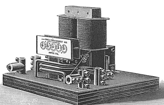
The story of the wattmeter stretches back to the work of Hungarian engineer Ottó Bláthy, who secured a patent for an alternating-current wattmeter, establishing one of the earliest foundations for measuring real electrical power in AC systems. For decades, electromagnetic designs dominated the field, handling utility-frequency and audio-frequency measurements with mechanical elegance. The landscape shifted dramatically in 1974, when Maghar S. Chana, Ramond L. Kraley, Eric A. Hauptmann Barry, and M. Pressman received a patent for an early electronic wattmeter. Their design relied on a combination of power, current, and voltage transformers working together to capture average power without the moving parts of their predecessors.
This electronic approach opened the door to measurements at frequencies well beyond what coil-based instruments could manage. Today, the wattmeter family spans a wide spectrum: electromagnetic types still serve utility and audio work, while entirely different sensor technologies—rectifier circuits, thermistors, bolometers, and even calorimeters—handle radio-frequency power measurement. The instrument has evolved from a single mechanical concept into a diverse toolkit, each variant tailored to a specific frequency band and power range.
The Electrodynamic Heart of the Analog Wattmeter
At the core of the classic analog wattmeter lies an elegant interplay between two sets of coils. A pair of fixed coils, called current coils, sits in series with the circuit under test, while a single movable coil—the potential coil—is wired in parallel. On the face of the instrument, the potential coil carries a needle that sweeps across a calibrated scale. When line current passes through the fixed coils, it generates an electromagnetic field whose strength tracks the current magnitude and stays in phase with it.
The potential coil, typically paired with a high-value series resistor to limit its own current, responds to the voltage across the circuit. In a direct-current setup, the needle's deflection scales with both current and voltage simultaneously, yielding the straightforward product P equals V times I. In alternating-current circuits, however, inductance and capacitance can shift the phase relationship between voltage and current. The electrodynamic mechanism naturally averages the instantaneous product over a full period, so the reading reflects active power P equals V I cos phi. The cosine of the phase angle—commonly called the power factor—reveals that the true power delivered can fall well short of the apparent power you would compute by simply multiplying a voltmeter reading by an ammeter reading.
Digital Sampling and the Non-Sinusoidal Problem
A modern digital wattmeter takes a fundamentally different approach: it samples both voltage and current thousands of times every second. At each sample instant, the voltage value is multiplied by the current value, and the average of those products over at least one complete cycle yields the real power in watts. From the same stream of sampled data, a computer circuit derives RMS voltage, RMS current, apparent volt-amperes, power factor, and cumulative kilowatt-hours.
These readings can appear on a local display, be stored as a log for averaging over longer periods, or be transmitted to external equipment for further analysis. Yet this digital sophistication hides a persistent weakness. When a load is highly reactive—such as an electric motor drawing substantial current while consuming relatively little real power—the gap between watts and volt-amperes widens dramatically, and wattmeters vary considerably in how correctly they handle that condition.
Many simple meters are calibrated to meet their stated accuracy only under ideal sinusoidal waveforms. The switched-mode power supplies found in most modern electronic equipment produce waveforms that deviate sharply from a sine shape, introducing unknown and potentially large errors at any power level. Manufacturers may not even disclose this limitation in the device manual.
The Low-Power Accuracy Gap and Practical Workarounds
Even a well-designed wattmeter runs into serious accuracy problems when the power under measurement drops to single-digit watt levels, a range typical of devices in standby or sleep mode. The difficulty stems primarily from the challenge of accurately measuring small alternating currents rather than small voltages, compounded by the relatively modest demand for such low-power readings in everyday practice. A typical plug-in meter might specify a wattage error of plus or minus five percent of the measured value plus ten watts. That means a reading of one hundred watts could actually be anywhere from eighty-five to one hundred and fifteen watts.
For energy, the error is stated as plus or minus five percent plus zero point one kilowatt-hours. The consequences become stark at the low end: a laptop in sleep mode drawing roughly five watts might register anywhere from zero to fifteen and a quarter watts on such a meter, before even accounting for waveform-related inaccuracies. One practical workaround is to connect a known fixed load—say, an incandescent light bulb—measure the combined draw, then subtract the bulb's contribution. This shifts the operating point out of the problematic low-power zone and into a range where the meter's accuracy specification is more meaningful.
Reader's Guide
The wattmeter's significance lies in its ability to measure true active power, distinguishing it from simple voltmeter and ammeter readings that only give apparent power. This is especially important in AC circuits where power factor reduces transmitted power. The development of electronic and digital wattmeters extended measurement capabilities to higher frequencies and provided greater accuracy through sampling techniques.
However, limitations exist: inexpensive meters may have large errors at low power (under 10 watts) and with non-sinusoidal waveforms common in switched-mode power supplies. Accuracy specifications typically include a percentage error plus a fixed wattage offset. The instrument's legacy includes integration into watthour meters that measure energy over time, and its principles underpin RF power measurement using bolometers and calorimeters across the entire radio spectrum.
Frequently Asked Questions
How does Wattmeter work under the hood?
The traditional analog model is an electrodynamic instrument that pairs fixed current coils with a moving element so the needle responds to the combined voltage-current interaction. For radio-frequency work, though, the physics shift enough that entirely different sensor architectures are required compared to the utility- or audio-frequency electromagnetic types.
What is Wattmeter's origin story?
The foundational idea grew out of Ottó Bláthy's early work on electrodynamic power measurement, and a landmark modern patent was filed in 1974 by Maghar S. Chana, Ramond L. Kraley, Eric A. Hauptmann Barry, and M. Pressman. That 1974 filing marks a key milestone in the instrument's evolution into the form used on test benches today.
More in RF Test Equipment
Sources
Compiled from Wikipedia and the sources listed below. Text from Wikipedia is available under CC BY-SA 4.0; this entry is adapted from it.
- Wikipedia: Wattmeter (CC BY-SA 4.0).
Spotted an error? Know more?
Reader corrections go straight into our review queue. Suggest an edit · How this site is sourced